Section 07 PROPULSION
Subsection 03 (REVERSE SYSTEM)
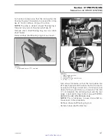
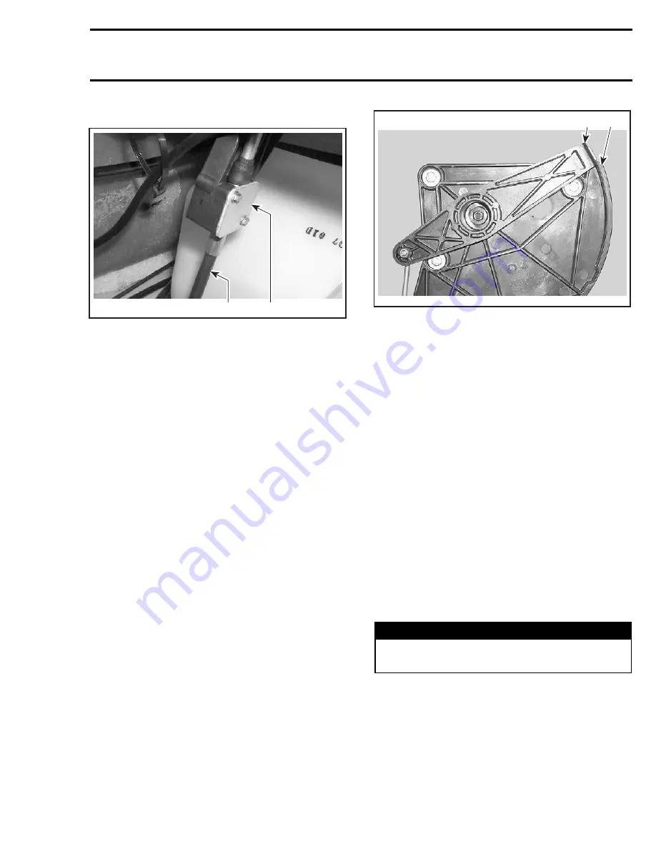
– bracket
no. 6
2
F16J0FA
1
TYPICAL
1. Bracket
2. Reverse cable
– bolts
no. 7
.
Withdraw reverse cable support
no. 8
.
Handle Housing
Remove:
– shift lever
– interior lever
– reverse cable support
– bolts
no. 9
.
Then, remove handle housing
no. 10
.
INSPECTION
Visually inspect parts for wear or cracks on friction
parts. Replace all defective parts.
ASSEMBLY
Assembly is essentially the reverse of disassem-
bly procedures. However pay particular attention
to the following.
When installing handle housing, apply Loctite 243
(blue) (P/N 293 800 060) on threads of screws.
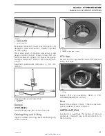
Insert interior lever cursor into reverse cable sup-
port slider and make sure that the cursor slides
freely in the slider.
1
F18J1LA
2
TYPICAL
1. Interior lever cursor
2. Reverse cable support slider
Interior Lever
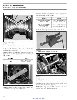
Apply synthetic grease (P/N 293 550 010) on the
interior lever pivot and in the reverse cable support
hole.
Install the interior lever in a rotating movement.
Engage properly the interior lever tabs in the shift
lever slots.
Make sure the shift lever action is smooth and
precise. Forward and reverse positions should be
easy to select with a decent position between
each.
Reverse Gate
Refer to JET PUMP section.
Reinstall removed parts.
ADJUSTMENT
Put shift lever in forward position.
WARNING
When adjusting reverse cable, make sure
lever is well engaged into the spring slot.
Place reverse gate in the up position.
Turn the joint at the end of reverse cable and align
its hole with hole in pivot arm.
Secure with bolt, washers, spacer and elastic stop
nut. Torque to 7 N•m (62 lbf•
in
).
smr2005-021
219
www.SeaDooManuals.net


