background image

Section 03

ENGINE

Sub-Section 05

(TOP END)

03-05-8

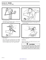
Clean piston ring grooves with a groove cleaner
tool, or a piece of broken ring.

INSPECTION

787 Engine

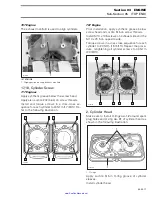
Check RAVE valve bellow 

no. 23

 for cracks.

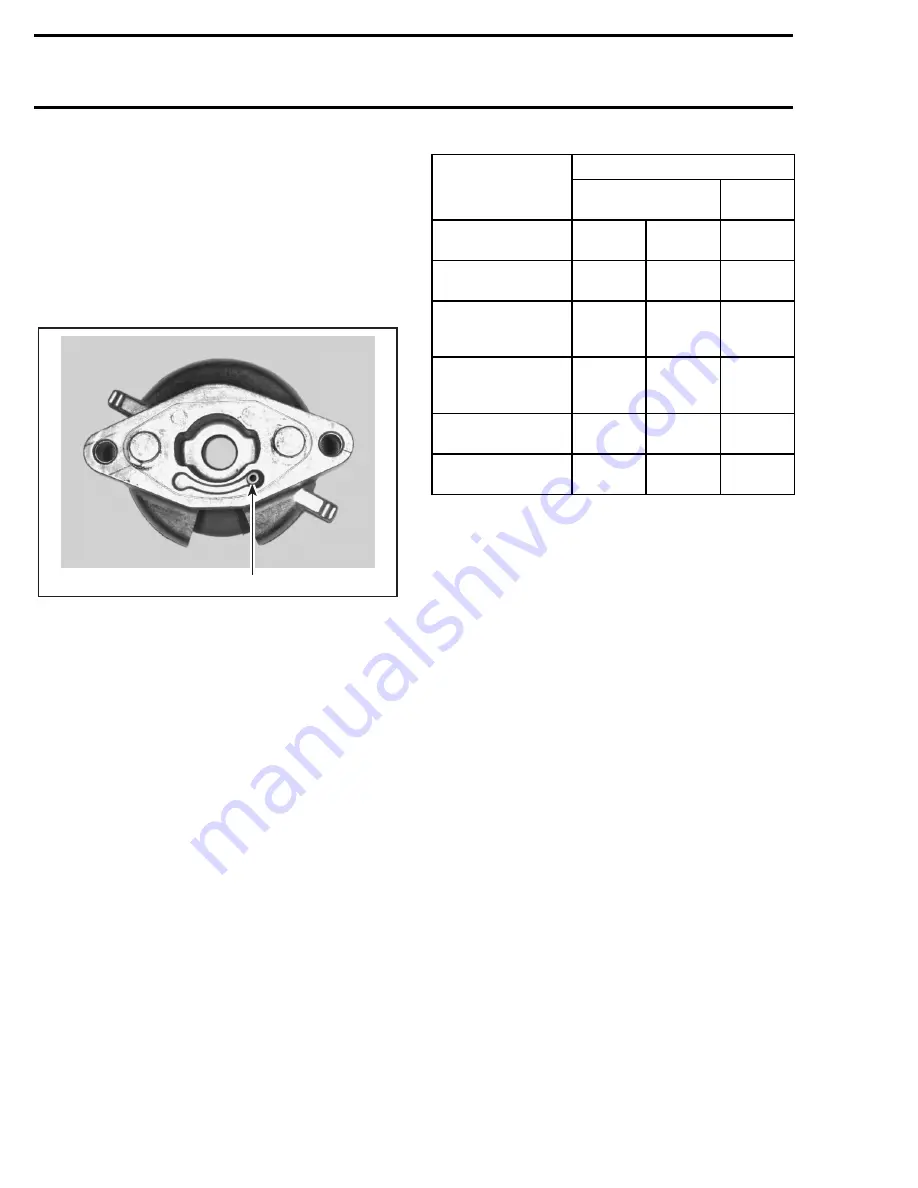
Check if passages of valve housing 

no. 27

 and cyl-

inder 

no. 9 

are not obstructed.

1. Passage of valve housing

All Engines

Visually inspect all parts for corrosion damage.

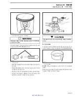
Inspect piston for damage. Light scratches can be
sanded with a fine sand paper.

NOTE:

When repairing a seized engine, connect-

ing rods should be checked for straightness and
crankshaft for deflection/misalignment. Refer to
ENGINE 03-06 for procedures. 

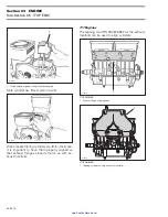
Inspect plane surfaces for warpage. Small defor-
mation can be corrected by grinding surface with
a fine sand paper. Install sand paper on a surface
plate and rub part against oiled sand paper.

The inspection of engine top end should include
the following measurements.

N.A.: Not Applicable

NOTE:

Replacement cylinder sleeves are avail-

able if necessary. Also, oversize pistons of 0.25
mm (.010 in) are available for all engines and over-
size pistons of 0.5 mm (.020 in) are available for
717 engines.

Cylinder Taper

Using a cylinder bore gauge, measure cylinder diam-
eter at 16 mm (5/8 in) from top of cylinder just below
auxiliary transfer port, facing exhaust port. If the dif-
ference between readings exceed specification, cyl-
inder should be rebored and honed or replaced.

F01D8JA

1

ENGINE

MEASUREMENT

TOLERANCES

NEW PARTS

(min.) (max.)

WEAR

LIMIT

Cylinder Taper

N.A.

0.05 mm

(.002 in)

0.1 mm

(.004 in)

Cylinder Out 
of Round

N.A.

0.008 mm

(.0003 in)

0.08 mm

(.003 in)

Piston/Cylinder Wall
Clearance for 
717 Engines

0.06 mm
(.0024 in)

0.11 mm

(.004 in)

0.20 mm

(.008 in)

Piston/Cylinder Wall
Clearance for the
787 Engine

0.10 mm

(.004 in)

0.12 mm

(.005 in)

0.20 mm

(.008 in)

Ring/Piston Groove 
Clearance 

0.03 mm

(.001 in)

0.07 mm

(.003 in)

0.20 mm

(.008 in)

Ring End Gap

0.25 mm

(.010 in)

0.40 mm

(.016 in)

1.0 mm

(.039 in)

www.SeaDooManuals.net

Summary of Contents for 1997 GSI

Page 1: ...www SeaDooManuals net ...

Page 2: ...0 0 SHOP MANUAL 0 219 100 048 www SeaDooManuals net ...

Page 3: ...uced in any form without the prior written permission of Bombardier Inc Bombardier Inc 1996 Printed in Canada Registered trademarks of Bombardier Inc Loctite is a trademark of Loctite Corporation Snap on is a trademark of Snap on Tools Corpo ration Gelcote is a trademark of Gelcote International Limited www SeaDooManuals net ...

Page 4: ...ection Pump 06 03 1 07 ELECTRICAL SYSTEM 01 Table of Contents 07 01 1 02 Ignition System 07 02 1 03 Charging System 07 03 1 04 Starting System 07 04 1 05 Instruments and Accessories 07 05 1 06 Digitally Encoded Security System 07 06 1 08 PROPULSION SYSTEM 01 Table of Contents 08 01 1 02 Jet Pump 08 02 1 03 Drive System 08 03 1 04 Reverse System 08 04 1 05 Variable Trim System 08 05 1 09 STEERING S...

Page 5: ... with new ones where specified If the efficiency of a locking device is impaired it must be renewed This manual emphasizes particular information denoted by the wording and symbols NOTE Indicates supplementary information needed to fully complete an instruction Although the mere reading of such information does not eliminate the hazard your understanding of the information will promote its correct...

Page 6: ...rd at the rear of the water craft 1 Hull Identification Number H I N All Models The Hull Identification Number is composed of 9 digits ENGINE IDENTIFICATION NUMBER H I N 717 Engines The Engine Identification Number is located on the upper side of the magneto housing TYPICAL 1 Engine Identification Number E I N F01L45A 1 F07A01A 1 Z Z N 1 2 3 4 5 L 4 9 5 Model year Serial number A letter may also b...

Page 7: ...NTENANCE 02 TROUBLESHOOTING 03 ENGINE 04 COOLING SYSTEM 05 FUEL SYSTEM 06 LUBRICATION SYSTEM 07 ELECTRICAL SYSTEM 08 PROPULSION SYSTEM 09 STEERING SYSTEM 10 SUSPENSION 11 HULL BODY 12 TECHNICAL DATA 13 WIRING DIAGRAMS Several sections are divided in various sub sections There is a table of contents at the beginning of many sections F01D87A 1 1997 BOMBARDIER WATERCRAFT SHOP MANUAL www SeaDooManuals...

Page 8: ...nd related positions TYPICAL PAGE F01A09S Illustration number for publishing process Sub section title indicates beginning of the sub section Dotted box contains parts of a particular model or an exploded view Page numbering system 03 ENGINE section 04 MAGNETO SYSTEM sub section 1 First page of this sub section Italic sub tiltle above exploded view indicate pertaining models Drop represents a liqu...

Page 9: ...pay attention that the rotary valve stay in place other wise it must be timed Remove carburetors from intake manifold Disconnect fuel bypass line between carburetors twin carburetors Remove carburetor s from rotary valve cover DISASSEMBLY AND INSPECTION Using a suitable pump gauge tester perform the fol lowing test proceeding as follows Install pump gauge tester P N 295 000 083 on pulse nipple Pum...

Page 10: ...gs ILLUSTRATIONS AND PROCEDURES The illustrations show the typical construction of the different assemblies and in all cases may not reproduce the full detail or exact shape of the parts shown however they represent parts which have the same or a similar function As many of the procedures in this manual are in terrelated we suggest that before undertaking any task you read and thoroughly understan...

Page 11: ...n 01 TABLE OF CONTENTS TABLE OF CONTENTS PERIODIC INSPECTION CHART 01 02 1 FLUSHING AND LUBRICATION 01 03 1 GENERAL 01 03 1 PROCEDURE 01 03 1 WATER FLOODED ENGINE 01 04 1 GENERAL 01 04 1 PROCEDURE 01 04 1 STORAGE 01 05 1 www SeaDooManuals net ...

Page 12: ... 787 engine Oil injection pump adjustment Fuel filter and oil filter inspection Fuel filter and oil filter replacement Engine head bolts retorque Steering system inspection Reverse system reverse cable adjustment if applicable Variable trim system if applicable Fastener tightening flame arrester support carburetor s engine mount exhaust system etc Muffler battery and reservoir fastening devices Fu...

Page 13: ...t and attach coupler hose P N 295 500 258 Make sure cou pler hose is properly locked to fitting spigot Install a hose pincher on water outlet hose TYPICAL 1 Coupler hose 2 Fitting spigot 3 Hose pincher Attach other end of coupler hose to a garden hose GS Series GTI and GTX Models Connect a garden hose to the water outlet located at the rear of the watercraft CAUTION Failure to flush cooling system...

Page 14: ...t a fast idle around 3500 RPM Pull plug from air intake silencer cover 1 Air intake silencer cover 2 Pull plug Spray BOMBARDIER LUBE lubricant through air intake silencer cover keeping engine at fast idle 1 Spray Bombardier Lube NOTE Lubrication of engine should be done at least for one minute F06E01A 1 F00E01A 1 F07E01A 1 CAUTION Always start the engine before opening the water tap Open water tap...

Page 15: ...GTS AND HX MODELS 1 Spark plug cables on grounding device SPX GS GSI GSX GTI AND GTX MODELS 1 Spark plug cables on grounding device XP MODEL 1 Grounding device Remove both spark plugs and spray BOMBAR DIER LUBE lubricant into each cylinder Crank the engine a few turns to distribute the oil onto cylinder wall Apply anti seize lubricant on spark plug threads then reinstall them Reinstall plug on air...

Page 16: ...BRICATION 01 03 4 NOTE Engine fogging should be done with BOMBARDIER LUBE lubricant whenever the wa tercraft is to be stored for a few days or a long period CAUTION Never leave rags or tools in the engine com partment or in the bilge www SeaDooManuals net ...

Page 17: ... Models 1 Spark plug cables on grounding device SPX GS GSI GSX GTI and GTX 1 Spark plug cables on grounding device XP Model 1 Grounding device All Models Remove spark plugs and dry them with a clean cloth A contact cleaner spray can be used It may be preferable to replace spark plugs Do NOT in stall spark plugs on engine Crank engine to drain crankcase CAUTION A water flooded engine must be proper...

Page 18: ...ition Start engine It may be necessary to use the choke If engine does not start repeat previous steps as necessary NOTE If engine does not start after several at tempts check ignition system for spark occur rence Refer to ELECTRICAL SYSTEM 07 02 Check crankshaft if needed it may be misaligned or deflected Refer to ENGINE 03 06 After engine has started spray BOMBARDIER LUBE lubricant through air i...

Page 19: ...d prior en gine lubrication to ensure carburetor protection against varnish deposit Always turn the fuel valve to OFF position when storing the watercraft Cooling System Flushing and Engine Internal Lubrication Cooling system has to be flushed with fresh wa ter to prevent salt sand or dirt accumulation which will clog water passages Engine must be lubricated to prevent corrosion on internal parts ...

Page 20: ...are available Re place damaged labels decals Wash the body with soap and water solution only use mild detergent Rinse thoroughly with fresh water Remove marine organisms from the hull Apply a nonabrasive wax If the watercraft is to be stored outside cover it with an opaque tarpaulin to prevent sun rays and grime from affecting the plastic components wa tercraft finish as well as preventing dust ac...

Page 21: ...e water craft to the rear so that water can flow out Additional Recommended Protection In cool regions where freezing point temperature may be encountered cooling system should be filled with water and antifreeze solution NOTE The engine will not have to run during this operation All Models Except XP and HX Three hoses have to be disconnected to allow air to escape and antifreeze solution to compl...

Page 22: ...d Insert a funnel into hose and pour about 1 liter 1 qt of antifreeze mixed with water in engine Remove temporary hose and reconnect engine water supply hose and engine water return hose Remove hose pincher All Models Most of the antifreeze will drain out when remov ing hose pinchers Use a container to recover it Dispose antifreeze as per your local laws and reg ulations NOTE Although antifreeze w...

Page 23: ...ded Seized jet pump Check refer to section 08 02 Engine turns slowly Discharged weak battery Check charge replace Restriction in jet pump Check clean pump Seizure in jet pump Inspect refer to section 08 02 Partial engine hydrolock Check refer to section 01 04 Partial engine seizure Check compression refer to section 03 05 Worn starter Check refer to section 07 04 Engine turns over Fuel water conta...

Page 24: ... to section 05 04 Loose main jet if applicable Check refer to section 05 04 Rotary valve shaft seal leaking Check replace refer to section 03 07 Oil pump adjustment Check adjust refer to section 06 03 Worn needle s and seal s Check refer to section 05 04 Excessive rotary valve clearance Check refer to section 03 07 Difficult to start Incorrect rotary valve timing Check adjust refer to section 03 0...

Page 25: ...ted crankshaft Check refer to section 03 06 Engine revs lower than its maximum operational RPM 787 engine RAVE valve does not open Check refer to section 03 05 Peak performance is delayed until higher RPM range is reached 787 engine RAVE valve is stuck opened Check refer to section 03 05 OTHER OBSERVATION POSSIBLE CAUSE REMEDY Engine RPM too high Faulty rev limiter Check refer to section 07 02 Imp...

Page 26: ...GENERAL 03 04 3 REMOVAL 03 04 3 CLEANING 03 04 6 DISASSEMBLY 03 04 6 ASSEMBLY 03 04 8 INSTALLATION 03 04 9 TOP END 03 05 1 GENERAL 03 05 3 DISASSEMBLY 03 05 5 CLEANING 03 05 7 INSPECTION 03 05 8 ASSEMBLY 03 05 11 ADJUSTMENT 03 05 18 BOTTOM END 03 06 1 CRANKSHAFT MISALIGNMENT AND DEFLECTION 03 06 3 DISASSEMBLY 03 06 4 CLEANING 03 06 7 INSPECTION 03 06 7 ASSEMBLY 03 06 9 ROTARY VALVE 03 07 1 GENERAL...

Page 27: ...E Sub Section 01 TABLE OF CONTENTS 03 01 2 EXHAUST SYSTEM 03 08 1 TUNED PIPE REMOVAL 03 08 4 EXHAUST MANIFOLD REMOVAL 03 08 6 MUFFLER REMOVAL 03 08 6 TUNED PIPE REPAIR 03 08 6 INSTALLATION 03 08 7 www SeaDooManuals net ...

Page 28: ...tion of soapy water on all hoses connections fittings plates etc If there is a leak bubbles will indicate leak location Three areas of the engine will be tested in se quence as per the diagnostic flow chart see the end of this sub section 1 Engine Cooling System 2 Bottom End and Top End 3 Rotary Valve Shaft NOTE If a leak is found it is important to contin ue testing as there is the possibility of...

Page 29: ... are not leaking and pressure drops verify all external jointed surfaces tem perature sensor and the O ring between the spark plug area and the engine cylinder head cover If none of these components are leaking there is an internal leak and it can be detected with Bottom End and Top End testing Bottom End and Top End Remove the carburetor s and gasket s Make sure the surface of the intake manifold...

Page 30: ...s If kit components are not leaking verify engine jointed surfaces as per following areas spark plugs cylinder head gasket cylinder base gasket crankcase halves rotary valve cover engine plugs exhaust manifold intake manifold 717 engines oil injection pump 717 engines Check also small oil injection pump lines and fit tings check for air bubbles or oil column going to ward pump which indicate a def...

Page 31: ...ose pincher Install pump with reducer and nipple to the oil supply hose of the rotary valve shaft 717 ENGINES 1 Pump with reducer and nipple 787 ENGINE 1 Pump with reducer and nipple Activate pump and pressurize to 5 PSI 34 kPa Check plug of the rotary valve shaft in crankcase Remove PTO side spark plug If pressure drops it indicates a defective PTO side crankshaft inner seal Remove MAG side spark...

Page 32: ...e the ro tary valve cover Check the seal of the rotary valve shaft If the rotary valve shaft is not leaking it could indi cates a defective engine casting Disassemble en gine and carefully check for defects in castings Pay attention to tapped holes which may go through sealed areas of engine and thus lead to leakage www SeaDooManuals net ...

Page 33: ...SEAL OF ROTARY VALVE SHAFT IS SEAL LEAKING CAREFULLY INSPECT ENGINE CASTINGS PARTICULARLY THE THREADED HOLE AREAS YES YES NO PRESSURIZE ENGINE COOLING SYSTEM IS SYSTEM LEAKING CHECK TESTING KIT REPLACE O RING OF CYLINDER HEAD AND OR CYLINDER BASE GASKET YES YES NO CHECK TESTING KIT IS RESERVOIR LEAKING PRESSURIZE ROTARY VALVE GEAR RESERVOIR IN CRANKCASE REPLACE GASKET OR O RING RE SEAL LEAKING ARE...

Page 34: ... battery holding straps and disconnect vent tube from battery Remove battery All Models Disconnect temperature switch wire and spark plug cables Disconnect magneto wiring harness TYPICAL 717 ENGINES 1 Unplug connector 787 ENGINE 1 Unplug connector Tuned Pipe To remove tuned pipe refer to ENGINE 03 08 Air Intake Silencer To remove air intake silencer refer to FUEL SYS TEM 05 03 Carburetor s All Mod...

Page 35: ...e can be easily lifted using the following suggested tools Cut porcelain from 2 old spark plugs Weld a lock washer approximately 20 mm di ameter on each spark plug as shown 1 Weld a lock washer 2 Old spark plug Remove spark plugs and replace by special tools Hook a sling into holes of special tools Using a chain block a hoist or other suitable equipment slightly lift engine to ease the remain ing ...

Page 36: ...all a hose pincher to oil return hose of rotary valve shaft then disconnect hose Disconnect RED positive cable from starter post TYPICAL 1 Disconnect RED positive cable Carry on engine lifting then tilt engine so that it can be removed from the body opening TYPICAL ALL ENGINES EXCEPT THE 787 CAUTION Take care not to damage cable or oil injec tion hoses F01D7PA 1 A01B2JB 1 CAUTION Be careful not to...

Page 37: ...y Loctite 242 blue on threads then torque nuts in a criss cross se quence to 35 N m 26 lbf ft TYPICAL 1 Torque to 35 N m 26 lbf ft Four Piece Engine Support Torque front and rear engine supports as shown in the following illustration 1 Torque screws to 22 N m 16 lbf ft 2 Torque nuts to 39 N m 29 lbf ft Oil Injection Hoses Make sure to reinstall hoses before completely lowering engine in bilge Posi...

Page 38: ...ws Install housing on hull with 4 nuts Carefully slide shaft through housing TYPICAL Insert shaft end into PTO flywheel NOTE Ensure the protective hose and carbon ring is removed to check engine alignment If the alignment is correct the shaft will slide easily without any deflection in PTO flywheel TYPICAL 1 Alignment shaft 2 PTO flywheel If the alignment is incorrect loosen engine sup port screws...

Page 39: ...dition and lubricate cable with BOMBARDIER LUBE lubricant After its in stallation properly adjust and bleed oil injection pump as specified in LUBRICATION SYSTEM 06 03 Check hose condition and pressure test fuel sys tem refer to FUEL SYSTEM 05 02 Verify all electrical connections Run engine and ensure there is no leakage CAUTION Whenever shims are used to correct align ment never install more than...

Page 40: ... in 9 9 N m 80 lbf in Loctite 242 10 11 12 Loctite 242 13 6 N m 53 lbf in Loctite 242 6 N m 53 lbf in 14 Loctite 242 15 6 N m 53 lbf in 4 16 Loctite 242 Loctite 648 5 6 145 N m 107 lbf ft Anti seize lubricant 2 9 N m 80 lbf in 1 3 4 N m 35 lbf in 17 18 SP GTS and HX models www SeaDooManuals net FLAT RATE PARTS ...

Page 41: ...e 242 Loctite 648 Loctite 648 10 7 9 6 5 8 1 2 4 11 10 N m 88 lbf in 10 N m 88 lbf in Synthetic grease Lithium grease 105 N m 77 lbf ft 10 N m 88 lbf in 6 N m 53 lbf in 10 N m 88 lbf in 9 N m 80 lbf in Anti seize lubricant 13 15 14 12 3 16 4 5 N m 40 lbf in www SeaDooManuals net FLAT RATE PARTS ...

Page 42: ...r plate 4 Sleeve Using 3 M8 x 35 screws P N 290 841 591 install screws through puller plate and slide sleeves on screws then secure puller plate on magneto fly wheel so that sleeves are against flywheel Install extension handle on end of puller plate TYPICAL 1 Sleeves on opposite side Using a suitable socket unscrew retaining nut no 6 COUNTERCLOCKWISE when facing it NOTE If socket is found too lar...

Page 43: ...gines Since replacement crankcases do not have timing mark for armature plate location indexing marks should be made on armature plate and crankcase to ease reassembly and further ignition timing The following procedure is to find a common ref erence point on both crankcases old and new to position armature plate Proceed as follows Find a crankcase locating lug the top one in this example Place a ...

Page 44: ... lug aligned with plate mark The new mark on crankcase will be used for fur ther assembly positioning as a pre timing posi tion TYPICAL 1 For further assembly use these marks 787 Engine 1 Magneto Housing Cover Loosen screws no 2 Remove engine magneto cover 4 5 Rotor and Flywheel Remove starter Refer to ELECTRICAL SYSTEM 07 04 Lock ring gear using special tool 1 Ring gear blocking tool P N 295 000 ...

Page 45: ...haft pro tective cap P N 290 876 557 Insert crankshaft protector to outer end of crank shaft and fully thread puller in engine flywheel 1 Puller Tighten puller screw and at the same time tap on screw head using a hammer to release engine fly wheel from its taper CLEANING Clean all metal components in a solvent Clean crankshaft taper and threads DISASSEMBLY 717 Engines 4 5 Magneto Flywheel and Ring...

Page 46: ...imp and unsolder BLACK RED wire from coil 1 Uncrimp and unsolder wire here 13 Battery Charging Coil To replace battery charging coil Heat the armature plate to 93 C 200 F around the screw holes to break the threadlocker bond 1 Heat the armature plate Remove screws Uncrimp and unsolder YELLOW and YEL LOW BLACK wires from coil CAUTION Protect harness from flame 1 F01D3AA F00D08A 1 CAUTION Protect ha...

Page 47: ...l Position new coil crimp and solder all wires Prior to assembly apply Loctite 242 blue Use magneto coil centering tool P N 290 876 922 and install it so that it fits around armature plate before tightening screws no 14 1 Magneto coil centering tool P N 290 876 922 4 5 Magneto Flywheel and Ring Gear Apply Loctite 648 green to magneto flywheel mating surface Lay ring gear on a steel plate then heat...

Page 48: ...TE The trigger coil is not adjustable 1 Trigger coil INSTALLATION 717 Engines 7 Magneto Housing Install gasket no 8 between magneto housing and engine crankcase Install magneto housing and torque screws no 9 to 9 N m 80 lbf in 10 Armature Plate Position the armature plate on the crankcase aligning the marks on both parts Apply a drop of Loctite 242 blue on threads of screws no 15 and torque to 6 N...

Page 49: ...e 648 to mating surfaces One of the protuberance end of magneto rotor must align with hole of engine flywheel 1 Protuberance 2 Hole Apply Loctite 648 green on screws no 11 and torque to 10 N m 88 lbf in Apply Loctite 242 blue on crankshaft taper Apply Loctite 242 blue on nut no 6 Install nut with lock washer and torque to 105 N m 77 lbf ft All Engines 1 Magneto Housing Cover Properly install O rin...

Page 50: ...17 Engines F00D0DS 24 N m 17 lbf ft 15 Loctite 242 Synthetic grease 28 1 12 2 17 Loctite 242 Synthetic grease 24 N m 17 lbf ft Loctite 515 9 16 Synthetic grease 6 5 34 rollers 4 3 8 7 7 8 3 4 5 6 34 rollers Synthetic grease www SeaDooManuals net FLAT RATE PARTS ...

Page 51: ... lbf ft Loctite 242 Synthetic grease 31 1 12 2 Synthetic grease 23 29 22 20 28 19 21 27 26 25 24 6 34 rollers 5 4 Synthetic grease 3 8 7 8 7 4 5 Synthetic grease 6 34 rollers 16 Loctite 515 Loctite 515 40 N m 30 lbf ft 18 Synthetic grease 9 30 www SeaDooManuals net FLAT RATE PARTS ...

Page 52: ...tuned for maximum power there is a large in crease of fresh charge losses As a result the torque decreases along with a dramatic increase of the specific fuel consumption Higher torque along with lower fuel consumption can be ob tained at lower engine speeds if the time the ex haust port is open is shortened Bombardier Rotax has patented a remarkably sim ple system to automatically change the exha...

Page 53: ...antaneous at item 7 Gradual application of the throttle however will result in the RAVE valve opening much later If the RAVE valve opens too late the engine will bog or hesitate momentarily as the RPM increas es Full peak performance item 6 is still available From a functional point of view It is better to have the valve open a bit early than a bit late MAINTENANCE There are no wear parts anywhere...

Page 54: ...and spark plug cables Connect spark plug cables on grounding device 717 Engines Remove air intake silencer and support refer to FUEL SYSTEM 05 03 All Engines Remove screws no 15 Remove cylinder head cover no 1 If shells sand salt or any other particles are present in cylinder head clean with a vacuum cleaner Remove cylinder head no 2 If shells sand salt water or any other particles are present in ...

Page 55: ...nder has been removed complete ly cover its opening with a clean rag 1 Openings covered with rag and rubber pad To remove circlip no 5 insert a pointed tool in pis ton notch then pry it out and discard TYPICAL 1 Piston notch To extract piston pin no 4 use piston pin puller P N 290 877 092 as follows Fully thread on puller handle Insert extractor spindle into the piston pin Slide the expansion slee...

Page 56: ...ully remove the piston no 3 The needles thrust washers and the expansion sleeve remain in the connecting rod bore and may be used again To remove rollers with the thrust washers from the connecting rod bore push them together with the expansion sleeve into the bushing P N 290 877 181 using any suitable 23 mm 905 in diam eter pusher 1 Pusher 23 mm 905 in CLEANING Discard all gaskets and O rings Cle...

Page 57: ...clude the following measurements N A Not Applicable NOTE Replacement cylinder sleeves are avail able if necessary Also oversize pistons of 0 25 mm 010 in are available for all engines and over size pistons of 0 5 mm 020 in are available for 717 engines Cylinder Taper Using a cylinder bore gauge measure cylinder diam eter at 16 mm 5 8 in from top of cylinder just below auxiliary transfer port facin...

Page 58: ...ced 1 Measuring in piston pin axis 2 Measuring perpendicularly 90 to piston pin axis A 16 mm 5 8 in Piston Cylinder Wall Clearance PISTON MEASUREMENT Used Piston Using a micrometer measure piston at 25 mm 1 in from skirt end perpendicularly 90º to piston pin 1 Measuring perpendicularly 90º to piston pin axis A 25 mm 1 in Lock the micrometer to the obtained value New Piston To determine the piston ...

Page 59: ...p edge 1 Measuring perpendicularly 90 to piston pin axis A 16 mm 5 8 in Read the measurement on the cylinder bore gauge The result is the exact piston cylinder wall clearance NOTE Make sure the cylinder bore gauge indica tor is set exactly at the same position as with the micrometer otherwise the reading will be false Ring Piston Groove Clearance Using a feeler gauge check clearance between rectan...

Page 60: ...askets are available for a precise adjustment of the combus tion chamber volume To determine gasket thickness refer to the identi fication holes on the gasket 1 Identification holes ASSEMBLY Assembly is essentially the reverse of disassem bly procedures However pay particular attention to the following 787 Engine 30 RAVE Valve Make sure to insert O ring no 25 onto rod of slid ing valve no 24 The T...

Page 61: ...e housing When the valve is mounted onto the cylinder move the valve piston no 22 to ensure the sliding valve no 24 moves easily and doesn t stick All Engines 3 Piston At assembly place the pistons over the connect ing rods with the letters AUS over an arrow on the piston dome facing in direction of the exhaust port 1 Exhaust side NOTE On the 787 engine the exhaust ports are located on the same si...

Page 62: ...on until it comes flush with inward edge of piston hub Warm piston to approximately 50 60 C 122 140 F and install it over connecting rod Insert extractor spindle into the piston pin screw on extracting nut Rotate handle to pull piston pin carefully into the piston Plastic Mounting Device Method This is an alternate method when no service tool is available Replacement roller bearings are delivered ...

Page 63: ...push out inner plastic ring on oppo site side Support piston from opposite side As necessary pull halves of inner sleeve with long nose pliers 1 Pulling inner sleeve half 5 Circlip Secure remaining circlip no 5 taking into consid eration the following F01D0VA 1 F01D0RA 1 2 CAUTION To minimize the stress on the circlips install them so that their openings are located at 6 o clock at bottom Always u...

Page 64: ...st piston pin opening Firmly hold piston against tool and push tool pusher to insert circlip into its groove 9 Cylinder To easily slide cylinder no 9 over piston no 3 in stall on piston ring compressor P N 290 876 979 1 Slide this edge NOTE Ring compressor will not fit on oversize parts Make sure to align ring end gap with piston locat ing pin Slide tool over rings WARNING Always wear safety glass...

Page 65: ...kcase it is important to have them properly aligned so that exhaust flanges properly match up with ex haust manifold 717 Engines The aligning tool P N 290 876 902 or the exhaust manifold can be used to align cylinders 717 ENGINES 1 Exhaust flange aligning tool 717 ENGINES 1 Aligning cylinders using exhaust manifold F01D0ZA 1 F01D10A F01D44A 1 F01D45A 1 www SeaDooManuals net ...

Page 66: ...llation apply synthetic grease below screw head and Loctite 515 on screw threads Install M10 x 105 screws on exhaust side and the M10 x 73 5 on opposite side Torque screws in a criss cross sequence for each cylinder to 20 N m 15 lbf ft Repeat the proce dure retightening all cylinder screws to 40 N m 30 lbf ft 2 Cylinder Head Make sure to install O rings no 12 around spark plug holes and O ring no ...

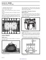
Page 67: ...er This will ensure the correct preload on the return spring no 29 in order to open and close the RAVE valve at the proper RPM Combustion Chamber Volume Measurement The combustion chamber volume is the region in the cylinder head above the piston at Top Dead Center It is measured with the cylinder head in stalled on the engine 1 Combustion chamber NOTE When checking the combustion chamber volume e...

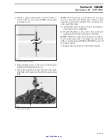
Page 68: ...lug hole NOTE The liquid level in cylinder must not drop for a few seconds after filling If so there is a leak between piston and cylinder The recorded vol ume would be false 5 Let burette stand upward for about 10 minutes until liquid level is stabilized 6 Read the burette scale to obtain the quantity of liquid injected in the combustion chamber NOTE When the combustion chamber is filled to top o...

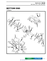
Page 69: ... Anti seize lubricant 15 14 1 6 5 6 Anti seize lubricant Loctite 642 15 2 Anti seize lubricant Loctite 242 6 6 4 1 Lithium grease Loctite 515 3 24 N m 17 lbf ft 9 11 Synthetic grease 7 24 N m 17 lbf ft 10 10 N m 88 lbf in Loctite 515 Loctite 515 Synthetic grease 8 40 N m 30 lbf ft www SeaDooManuals net FLAT RATE PARTS ...

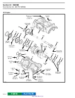
Page 70: ...t Anti seize lubricant 14 Loctite 242 Loctite 642 Anti seize lubricant Lithium grease Loctite 515 Loctite 515 Synthetic grease 8 40 N m 30 lbf ft Loctite 515 Synthetic grease 7 24 N m 17 lbf ft Loctite 515 Synthetic grease 8 40 N m 30 lbf ft 24 N m 17 lbf ft Synthetic grease 30 mL 1 oz SAE 30 motor oil 5 6 2 6 12 12 2 6 4 6 3 7 17 15 15 13 18 www SeaDooManuals net FLAT RATE PARTS ...

Page 71: ...proceed as follows Remove magneto housing cover Remove flywheel nut and magneto rotor for the 787 engine Refer to ENGINE 03 04 for procedures Install Bombardier degree wheel P N 295 000 007 on crankshaft end Hand tighten nut only Remove both spark plugs Install a TDC gauge in spark plug hole on MAG side Bring MAG piston at Top Dead Center As a needle pointer secure a wire with a cover screw and a ...

Page 72: ...engine PTO flywheel refer to PROPULSION SYSTEM 08 03 NOTE PTO flywheel must be removed prior re moving MAG flywheel magneto flywheel refer to ENGINE 03 04 starter magneto housing rotary valve cover and valve crankcase retaining screws Insert screwdrivers between crankcase lugs and pry to separate halves being careful not to dam age precision machined surfaces 1 Separate halves by prying at provide...

Page 73: ...ved in one step using another puller See Crankshaft Gear no 13 1 Puller P N 290 876 298 2 Protective cap P N 290 876 557 3 Distance ring P N 290 876 569 4 Ring P N 290 977 490 5 Ring halves P N 290 977 475 6 Screw M8 x 40 P N 290 840 681 7 Screw M8 x 70 P N 290 841 201 NOTE To facilitate ring or distance ring installa tion lubricate their inside diameters All Engines TYPICAL 1 Removing crankshaft ...

Page 74: ...aft Bearings no 12 can be removed by using the fol lowing tools 1 Puller P N 290 876 298 2 Protective cap P N 290 876 557 3 Ring P N 290 977 480 4 Ring halves P N 290 876 330 5 Screw M8 x 40 P N 290 840 681 1 Tool installed To remove gear no 18 first trace an index mark on the gear and counterbalance shaft NOTE There is no Woodruff key to position the gear on the counterbalance shaft An index mark...

Page 75: ...lastic cage is not melted Rotate and make sure they turn smoothly If crankshaft and or components are found defec tive it must be repaired by a specialized shop or replaced The inspection of engine bottom end should in clude the following measurements Connecting Rod Straightness Align a steel ruler on edge of small end connect ing rod bore Check if ruler is perfectly aligned with edge of big end 1...

Page 76: ...ent or twisted crankshaft at connecting rod journal 1 Measuring PTO side deflection in crankcase 1 Measuring MAG side deflection in crankcase Remove crankshaft bearings and check deflection again on V shaped blocks as illustrated 1 Measuring MAG side deflection on V shaped blocks 1 Measuring PTO side deflection on V shaped blocks NOTE Crankshaft deflection can not be correctly measured between cen...

Page 77: ...nstallation To properly position the outer PTO side bearing no 5 on 717 engines or the outer MAG side bear ing no 4 on the 787 engine a distance gauge must be temporarily installed against the inner bearing Slide the outer bearing until stopped by the distance gauge then remove it 1 Distance gauge TYPICAL 1 Distance gauge 2 Outer bearing 15 Distance Ring When installing the distance ring make sure...

Page 78: ...ensure proper lubrication of the bearing 1 Seal against the retaining shim All Engines 6 Drive Pin Make sure drive pins of bearings are properly in stalled in crankcase recesses at assembly 1 Drive pin 787 Engine 16 18 Counterbalance Shaft and Gear Press gear no 18 onto counterbalance shaft tak ing care to align both marks previously traced F00D0LA 1 F00D0MA 1 2 CAUTION Counterbalance shaft must b...

Page 79: ...ner filled with oil previously heated to 75 C 167 F This will expand bearings and ease their installa tion 14 16 Crankshaft and Counterbalance Shaft Install crankshaft first in crankcase After crankshaft installation install counterbal ance shaft Make sure to properly index crank shaft and counterbalance shaft by aligning marks of gears 1 Marks must be aligned Turn by hand the crankshaft and count...

Page 80: ... head screws Torque crankcase screws to 24 N m 17 lbf ft as per following illustrated sequence 8 Crankcase Screw Torque 2 M10 crankcase screws to 40 N m 30 lbf ft 1 Torque to 40 N m 30 lbf ft 10 Stud At assembly in crankcase apply Loctite 515 on stud threads Torque to 10 N m 88 lbf in 787 Engine 7 8 Crankcase Screw Apply Loctite 515 on screw threads and synthetic grease below head screws Torque cr...

Page 81: ...PPORT If engine support is installed on crankcase before magneto housing electric starter must be in stalled before engine support 1 Install starter before engine support 787 Engine When engine assembly is completed add 30 mL 1oz of motor oil SAE 30 to the counterbalance shaft gear through the crankcase filler plug 1 Add oil here F01D81A 11 7 21 1 22 3 5 9 10 6 14 2 4 13 8 12 19 17 15 16 18 20 F01...

Page 82: ...Sub Section 07 ROTARY VALVE 03 07 1 ROTARY VALVE 0 F01D7SS 8 2 20 N m 15 lbf ft Lithium grease 1 7 10 6 9 5 11 3 4 13 12 14 15 1 787 Engine 717 Engines 2 13 12 1 20 N m 15 lbf ft 12 www SeaDooManuals net FLAT RATE PARTS ...

Page 83: ... valve cover clearance One with a 45 feeler gauge the other one with a solder 45 FEELER GAUGE METHOD Remove O ring from rotary valve cover Remove intake manifold from rotary valve cover except 787 engine Reinstall cover in place WITHOUT its O ring and torque screws to 20 N m 15 lbf ft Feeler gauge blade from 0 25 mm 010 in to 0 35 mm 014 in thickness should fit between rotary valve and cover Inser...

Page 84: ... AND O RING GROOVE BASE 1 Cover seating surface 2 O ring groove depth must be 1 0 0 03 mm 039 001 in Reverify the clearance At assembly the rotary valve timing must remain as per original setting NOTE If rotary valve crankcase surface is worn it is possible to have it reworked at the factory Contact your dealer or distributor Rotary Valve Shaft Gear Backlash Remove PTO flywheel guard Remove spark ...

Page 85: ... over rotary valve shaft end and screw on puller bolt into shaft While retaining bolt with a wrench turn puller nut CLOCKWISE until shaft comes out 1 Hold bolt 5 6 Circlip and Spring Seat If it is necessary to disassemble components of rotary valve shaft assembly use seat to compress spring and remove circlips 1 Compress seat 2 Remove circlips CAUTION Bottom end must be opened to remove rota ry va...

Page 86: ...ring Holding claws turn puller shaft clockwise so that claws open and become firmly tight against bearing Slide puller sleeve outwards and tap puller end Retighten claws as necessary to always maintain them tight against bearing Continue this way un til bearing completely comes out 1 End bearing CLEANING Discard all seals and O rings Clean all metal components in a solvent Clean oil passages and m...

Page 87: ...or presence of brass filings in gear hous ing Rotary Valve Shaft Deflection Deflection is measured with a dial gauge Install rotary valve shaft in crankcase half without its gear NOTE End bearing must be in crankcase half Measure shaft deflection next to gear splines 1 Rotary valve shaft 2 End bearing in place Deflection must not exceed 0 08 mm 003 in Replace shaft as necessary ASSEMBLY Assembly i...

Page 88: ...llustrated 1 Seal 2 Ball bearing 3 Bearing extractor Snap on CJ 950 Install shim no 15 snap ring no 7 and slide dis tance sleeve no 14 on shaft 1 Seal 2 Ball bearing 3 Snap ring 4 Distance sleeve 5 Shim 0 5 mm 020 in 6 Rotary valve shaft 3 Rotary Valve Shaft Assembly F01D2DA 1 F01D33A 1 2 CAUTION Crankcase halves must be separated and crankshaft must not be present to install ro tary valve shaft a...

Page 89: ...g seat All Engines 4 Snap Ring Position snap ring so that its sharp edge faces out wards 13 Rotary Valve The rotary valve controls the opening and closing of the inlet ports Therefore its efficiency will de pend on the precision of its installation IDENTIFICATION OF THE ROTARY VALVE There is no identification code on the valves To find out the duration place an angle finder on the valve and measur...

Page 90: ...Section 03 ENGINE Sub Section 07 ROTARY VALVE 03 07 9 F01D8SS 159 cut out angle TEMPLATE 290 924 502 actual size 159 cut out angle 132 cut out angle 290 924 504 actual size www SeaDooManuals net ...

Page 91: ...port Align 360 line of degree wheel Step Find 147 on degree wheel and mark here NOTE Do not rotate the crankshaft For closing mark first align 360 line of degree wheel with TOP of MAG side inlet port Then find 65 line on degree wheel and mark crank case at this point CAUTION Never use the ridge molded in crankcase as a timing mark ENGINE TIMING OPENING BTDC CLOSING ATDC 717D 130 5 55 5 717 147 5 6...

Page 92: ...asymmetrical Therefore try flipping it over then reinstall on splines to ob tain best installation position Apply BOMBARDIER ROTAX injection oil on rota ry valve before reassembling rotary valve cover Remove TDC gauge 1 Rotary Valve Cover Install O ring no 12 and cover then torque screws no 2 to 20 N m 15 lbf ft in a criss cross sequence NOTE For the 717D engine SP model install engine in watercra...

Page 93: ...ease 17 17 19 18 24 14 24 N m 17 lbf ft 9 Loctite 242 7 25 N m 18 lbf ft 9 8 25 N m 18 lbf ft Loctite 242 11 SP model 19 18 19 Loctite 242 6 25 N m 18 lbf ft 5 6 25 N m 18 lbf ft 22 10 N m 88 lbf in 21 2 3 13 1 4 N m 35 lbf in 4 N m 35 lbf in 27 N m 20 lbf ft Sealant 732 19 Loctite 242 15 www SeaDooManuals net FLAT RATE PARTS ...

Page 94: ...tite 242 9 7 25 N m 18 lbf ft Loctite 242 9 19 10 10 N m 88 lbf in 4 16 Sealant 736 25 N m 18 lbf ft 6 Loctite 242 12 4 N m 35 lbf in 1 3 4 N m 35 lbf in 14 24 N m 17 lbf ft Synthetic grease Loctite 592 9 15 20 17 4 N m 35 lbf in 2 4 N m 35 lbf in 13 19 18 25 www SeaDooManuals net FLAT RATE PARTS ...

Page 95: ...19 12 16 4 Sealant 736 10 N m 88 lbf in 10 9 Loctite 242 8 40 N m 30 lbf ft 7 40 N m 30 lbf ft 9 Loctite 242 Loctite 648 17 24 15 Loctite 515 14 40 N m 30 lbf ft 14 40 N m 30 lbf ft 24 Synthetic grease 20 2 Sealant 732 27 N m 20 lbf ft Sealant 732 7 N m 62 lbf in XP SPX GSX GTX 4 N m 35 lbf in 4 N m 35 lbf in 4 N m 35 lbf in www SeaDooManuals net FLAT RATE PARTS ...

Page 96: ... lift tuned pipe to release nut as necessary Take care not drop nut and flat washer Withdraw tuned pipe head no 11 in a forward and rotating movement HX and XP Models Only NOTE It is possible to remove the tuned pipe head and cone at the same time If such is the case disconnect only the water outlet hose at cyl inder head and do not remove the clamp retaining tuned pipe head to tuned pipe cone Dis...

Page 97: ...exhaust hose collar no 1 at tuned pipe cone outlet Remove clamp no 4 securing tuned pipe cone to tuned pipe head Remove screws no 7 and nut no 8 with flat washers no 9 at tuned pipe head flange Remove retaining screw no 23 of tuned pipe head 1 Screw Remove tuned pipe head no 10 Remove both screws no 6 retaining tuned pipe cone to engine F01D3YA 2 1 F01D7IA F01D76A 1 F01D7KA F01D7LA www SeaDooManua...

Page 98: ...bilge HX Model Only Loosen exhaust hose collar no 1 at tuned pipe cone outlet only if tuned pipe cone is not re moved Remove rear access cover from body Disconnect upper exhaust hose no 25 in front of muffler Disconnect both water injection hoses and both water drain hoses from muffler Disconnect retaining strap no 2 of muffler 1 Strap Pull muffler no 13 out of bilge NOTE Lower exhaust hose of muf...

Page 99: ...ce 787 Engine Apply Loctite 515 on two screws no 14 On the other screws no 14 apply synthetic grease on threads Install screws Refer to the following il lustration for proper position of screws to the ex haust manifold 1 Screw with Loctite 515 2 Screw with synthetic grease Torque exhaust manifold screws to 24 N m 17 lbf ft as per following illustrated sequence Re peat the procedure retightening sc...

Page 100: ...ustration for the torquing sequence TYPICAL Step Torque screw s of tuned pipe cone to 12 N m 9 lbf ft Step Torque nut and screws of tuned pipe flange in a criss cross sequence to 12 N m 9 lbf ft Step Repeat the torquing sequence by retightening all fasteners to 25 N m 18 lbf ft Step Torque clamp to 10 N m 88 lbf in if applicable 787 Engines Torque nut no 8 and screws no 7 of tuned pipe head flange...

Page 101: ...in alignment Push cone no 5 until it touches tuned pipe then tighten exhaust clamp no 22 and torque to 10 N m 88 lbf in NOTE Exhaust clamp nuts should be tightened alternately to assure no leakage and to obtain specified torque CAUTION There must be no gap between tuned pipe cone and tuned pipe head www SeaDooManuals net ...

Page 102: ...OOLING SYSTEM Sub Section 01 TABLE OF CONTENTS TABLE OF CONTENTS COMPONENTS 04 02 1 GENERAL 04 02 6 CIRCUIT 04 03 1 GENERAL 04 03 1 717 ENGINE COOLING SYSTEM 04 03 4 787 ENGINE COOLING SYSTEM 04 03 5 www SeaDooManuals net ...

Page 103: ...MPONENTS 0 SP and GTS Models F01E1PS Loctite 592 3 Loctite 592 Loctite 592 SP model only 1 2 N m 11 lbf in Loctite 592 Loctite 592 1 2 N m 11 lbf in 2 1 1 1 2 N m 11 lbf in 2 5 N m 22 lbf in 1 2 N m 11 lbf in 1 2 N m 11 lbf in www SeaDooManuals net FLAT RATE PARTS ...

Page 104: ...bf in Loctite 592 Loctite 592 Loctite 592 Loctite 592 Loctite 592 1 2 1 1 1 2 N m 11 lbf in 2 N m 18 lbf in 1 2 N m 11 lbf in 1 1 1 2 N m 11 lbf in 4 Loctite 592 2 5 N m 22 lbf in Loctite 592 6 5 9 10 0 11 N m 1 lbf in 0 6 N m 5 lbf in 8 7 Loctite 592 5 N m 44 lbf in www SeaDooManuals net FLAT RATE PARTS ...

Page 105: ...ction 02 COMPONENTS 04 02 3 GS GSI and GTI Models F00E02S Loctite 592 3 Loctite 592 Loctite 592 1 1 1 2 N m 11 lbf in 1 2 N m 11 lbf in 1 2 N m 11 lbf in 1 2 N m 11 lbf in Loctite 592 Loctite 592 www SeaDooManuals net FLAT RATE PARTS ...

Page 106: ... Loctite 592 1 2 N m 11 lbf in 1 2 N m 11 lbf in 1 1 2 N m 11 lbf in 3 Loctite 592 Loctite 592 Loctite 592 Loctite 592 0 6 N m 5 lbf in 8 5 N m 44 lbf in 7 Loctite 592 10 0 11 N m 1 lbf in 6 9 5 Loctite 592 0 11 N m 1 lbf in Loctite 592 1 2 N m 11 lbf in www SeaDooManuals net FLAT RATE PARTS ...

Page 107: ...TS 04 02 5 HX Model F05E04S Loctite 592 Loctite 592 1 2 N m 11 lbf in Loctite 592 1 1 2 N m 11 lbf in Body Loctite 592 1 2 N m 11 lbf in 1 1 2 N m 11 lbf in 1 Loctite 592 Engine water outlet 1 Engine water outlet www SeaDooManuals net FLAT RATE PARTS ...

Page 108: ...injection also helps in reducing noise level and cools components of the exhaust sys tem The elbow fitting can be identified by using the number stamped onto the fitting or by measuring its inside diameter Refer to the following illustra tion and chart TYPICAL 1 Outlet diameter 4 6 mm 181 in 2 Stamped number 3 Inlet diameter 5 5 mm 219 in CAUTION All hoses and fittings of the cooling system have c...

Page 109: ...ed water pressure increases in the supply hose of the regulator valve and gradually overcomes the return spring of the regulator valve Less water is being delivered to the injec tion fitting at the tuned pipe Adjustment The water flow regulator valve has been calibrat ed at the factory and should not be modified NOTE Water flow regulator valves ordered from the parts channel are also calibrated If...

Page 110: ...g Remove fitting from valve housing 1 Fitting 8 Tapered Needle Unscrew the tapered needle NOTE Hold the valve to prevent it from turning 1 Tapered needle Remove the tapered needle from valve housing 1 Remove tapered needle F01E1RA 1 2 F01E1SA 1 F01E1TA 1 F01E20A 1 www SeaDooManuals net ...

Page 111: ... pliers release the clamp which retains the bellows Remove valve and bellows Loosen clamp to separate valve from bellows 1 Clamp Inspection Inspect parts for damage Verify especially bel lows for cracks Assembly Assembly is essentially the reverse of disassem bly procedures F01E21A F01E24A 1 www SeaDooManuals net ...

Page 112: ...ing speed is 24 km h 15 MPH When towing your watercraft pinch the water supply hose from the impeller housing to the en gine with the Hose Pincher large P N 529 030 400 This will prevent the cooling system from filling which may lead to water being injected into and filling the exhaust system Without the engine running there isn t any exhaust pressure to carry the water out the exhaust outlet Snug...

Page 113: ...tion Water is pre heated by the exhaust system before entering the cylinder cooling jackets Water enters cylinder cooling jacket through pas sages located below exhaust ports from tuned pipe 1 Water passages No water enters crankcase When engine is running water must flow from bleed outlet indicating that water circulates When servicing the hull always rotate watercraft counterclockwise seen from ...

Page 114: ... pages for each engine model F01E1GA 1 F01E0FB 1 CAUTION Never modify cooling system arrangement oth erwise serious engine damage could occur TECHNICAL DATA TYPE TLCS Total Loss Cooling System COOLANT FLOW Pressure build up at impeller housing no water pump TEMPERATURE CONTROL Calibrated outlet fittings no thermostat SYSTEM BLEEDING Self bleed type hose at uppermost point of circuit SYSTEM DRAININ...

Page 115: ...tor CSI small stream of water flows out of bleed outlet located near stern eyelet Calibrated outlet fittings limit water flow Pressure zone Tuned pipe bleed hose injects water into muffler to cool exhaust components Lowest point of circuit allows draining whenever engine is stopped Water injected directly into exhaust gas for noise reduction and performance improvement Water flows through tuned pi...

Page 116: ...n temperature exceeds 96 99 C 205 210 F Calibrated cylinder head limits water flow Water flows through tuned pipe and manifold water jackets Water regulated by the water flow regulator valve and injected directly into exhaust gas for noise reduction and performance improvement Lowest point of circuit allows draining whenever engine is stopped Water inlet hose of valve Water directly injected into ...

Page 117: ...MOVAL 05 02 7 INSPECTION 05 02 9 ASSEMBLY 05 02 10 FUEL SYSTEM PRESSURIZATION 05 02 10 AIR INTAKE 05 03 1 REMOVAL 05 03 2 ASSEMBLY 05 03 2 CARBURETORS 05 04 1 GENERAL 05 04 3 REMOVAL 05 04 3 CLEANING 05 04 4 DISASSEMBLY AND INSPECTION 05 04 4 ASSEMBLY 05 04 5 INSTALLATION 05 04 8 ADJUSTMENTS 05 04 9 www SeaDooManuals net ...

Page 118: ... FUEL CIRCUIT 0 SP and GTS Models F01F19S 2 N m 18 lbf in 6 N m 53 lbf in 7 6 1 N m 9 lbf in 4 22 N m 16 lbf ft 4 N m 35 lbf in 5 4 4 N m 35 lbf in 3 N m 27 lbf in 8 SP model Loctite 242 3 N m 27 lbf in 1 2 3 12 11 10 9 13 www SeaDooManuals net FLAT RATE PARTS ...

Page 119: ... CIRCUIT 05 02 2 SPX Model F01F2ZS 3 3 N m 27 lbf in 1 2 2 N m 18 lbf in 6 N m 53 lbf in 7 6 1 N m 9 lbf in 3 N m 27 lbf in 10 12 11 5 4 N m 35 lbf in 4 22 N m 16 lbf ft 4 N m 35 lbf in 4 13 8 9 Engine Body www SeaDooManuals net FLAT RATE PARTS ...

Page 120: ...UIT 05 02 3 GS GSI and GTI Models F00F09S 3 N m 27 lbf in 3 6 N m 53 lbf in 1 2 7 6 1 N m 9 lbf in 5 4 22 N m 16 lbf ft 4 N m 35 lbf in 4 4 N m 35 lbf in 9 8 3 N m 27 lbf in 12 11 10 2 N m 18 lbf in Body Engine www SeaDooManuals net FLAT RATE PARTS ...

Page 121: ...2 FUEL CIRCUIT 05 02 4 GSX and GTX Models F06F03S Body 6 7 2 N m 18 lbf in 3 N m 27 lbf in 6 N m 53 lbf in 3 1 2 1 N m 9 lbf in 10 11 12 3 N m 27 lbf in 5 4 4 N m 35 lbf in 22 N m 16 lbf in 8 9 Engine www SeaDooManuals net FLAT RATE PARTS ...

Page 122: ...UIT 05 02 5 HX and XP Models F05F09S Body 1 3 2 7 2 N m 18 lbf in 3 N m 27 lbf in 6 N m 53 lbf in Body 6 1 N m 9 lbf in 12 11 10 3 N m 26 lbf in 4 4 N m 35 lbf in 5 4 4 N m 35 lbf in 22 N m 16 lbf in 8 9 Engine www SeaDooManuals net FLAT RATE PARTS ...

Page 123: ... pliers P N 295 000 070 1 Cutting clamp 1 Securing clamp 1 Securing clamp in limited access When replacing fuel lines on SEA DOO water craft be sure to use B1 hoses as available from Bombardier parts department This will ensure continued proper and safe operation WARNING Whenever repairing the fuel system always verify for water infiltration in reservoir WARNING Replace any damaged leaking or dete...

Page 124: ...cap to remove any fuel pres sure in system Unscrew the fuel filter bowl no 2 counterclock wise then pull toward the bottom TYPICAL Step Loosen counterclockwise Step Pull Pull fuel filter no 1 toward the bottom TYPICAL 8 Fuel Baffle Pick Up NOTE The baffle pick up has an integrated fuel sensor on models which have a fuel gauge WARNING The engine must not be running and fuel valve must be set to OFF...

Page 125: ...t cover Remove storage basket from watercraft Remove steering assembly Refer to STEERING SYSTEM 09 04 GTI and GTX Models Remove glove box HX Model Pull down left vent tube 1 Vent tube Cut tie rap retaining fuel hoses to tie mount 1 Cut tie rap XP Model Tilt seat Refer to HULL BODY 11 02 Remove access plug on body All Models Remove hoses from baffle pick up and disconnect wiring harness of fuel sen...

Page 126: ...ositioned into the filter bowl no 2 1 Gasket in bowl 5 Filler Neck Hose Verify fuel filler neck hose for damage Always en sure that clamps no 4 are well positioned and tightened Torque clamps to 4 N m 35 lbf in 6 Pressure Relief Valve This valve will eliminate fuel spillage when the watercraft is upside down If pressure is built up in fuel system the valve should open at 10 kPa 1 5 PSI to release ...

Page 127: ...he mark on the fuel tank 1 Baffle pick up notch 2 Fuel tank mark GTS Model Only Insert vent tube in body and clip it in place 1 Install vent tube FUEL SYSTEM PRESSURIZATION Pressure Test Proceed as follows Fill up fuel tank Disconnect air inlet hose of fuel tank from body Install a hose pincher P N 295 000 076 on fuel tank vent hose WARNING Vent tube must be in place to provide proper bilge ventil...

Page 128: ... spray a solution of soapy water on com ponents bubbles will indicate leak location NOTE The system must maintain a pressure of 34 kPa 5 PSI during 10 minutes Never pressur ize over 34 kPa 5 PSI Reconnect air inlet hose of fuel tank to body NOTE Before removing the hose pincher block with your finger the outlet fitting to feel if air is coming out when removing hose pincher This will indicate that...

Page 129: ...INTAKE 05 03 1 AIR INTAKE 0 F01F1WS 1 9 4 8 10 N m 88 lbf in 8 Loctite 242 Loctite 242 6 Loctite 242 2 10 N m 88 lbf in 5 Twin carbs 10 7 Loctite 515 3 Single carb Loctite 515 7 Loctite 242 10 N m 88 lbf in www SeaDooManuals net FLAT RATE PARTS ...

Page 130: ...me arrester base to the cylinder head cover 717 engines or to the exhaust manifold 787 en gine 1 Remove support Remove screws no 10 from flame arrester base then withdraw base NOTE On single Mikuni carburetor models re move choke and throttle cables from flame arrest er base ASSEMBLY Assembly is essentially the reverse of removal procedures However pay particular attention to the following 7 Flame...

Page 131: ...ition of flame arrester Replace or clean as necessary 787 Engine Position the flame arrester with its embossment toward TOP 9 Gasket Inspect condition of gasket Make sure to proper ly installed gasket WARNING Do not operate watercraft without flame ar rester F00F04A www SeaDooManuals net ...

Page 132: ...EL SYSTEM Sub Section 04 CARBURETORS 05 04 1 CARBURETORS 0 Mikuni BN 38 F02F0KS 12 3 11 10 9 8 1 13 14 7 Loctite 242 4 19 5 15 Anti seize lubrifiant Loctite 242 6 2 13 18 17 16 www SeaDooManuals net FLAT RATE PARTS ...

Page 133: ...S 05 04 2 Mikuni BN 38I BN 40I F01F05S Loctite 242 6 14 Loctite 242 20 21 20 N m 15 lbf ft MAG 13 Loctite 242 7 15 Anti seize lubricant 19 5 4 18 17 16 PTO Synthetic grease Synthetic grease 2 13 1 8 10 9 11 3 12 www SeaDooManuals net FLAT RATE PARTS ...

Page 134: ...o FUEL SYS TEM 05 03 Turn fuel valve to OFF position Disconnect pulse line TYPICAL 1 Pulse line Disconnect fuel supply line from fuel pump Disconnect fuel return line Disconnect oil injection pump cable throttle cable and choke cable BN 38 Carburetor Remove 4 bolts and lock washers from rotary valve cover then move carburetors and rotary valve on top of engine NOTE When removing rotary valve cover...

Page 135: ...est proceeding as follows Install pump gauge tester P N 295 000 114 on pulse nipple Pump tester until it reaches 28 kPa 4 PSI TYPICAL 1 Pump gauge tester 2 Install on pulse nipple Diaphragm must stand pressure for 10 seconds If pressure drops replace diaphragm 4 Pump Body Check fuel pump valve operation as follows Connect a clean plastic tubing to the inlet nipple and alternately apply pressure an...

Page 136: ...ully with compressed air low pressure Replace filter if damaged TYPICAL 1 Filter ASSEMBLY When assembling pump ensure to properly posi tion components together Refer to previous illus trations if necessary 6 7 Choke Plate and Throttle Plate When installing plate onto shaft close plate so that it centers into carburetor bore Firmly tighten screws 8 Needle Valve Lever Rounded end of needle valve lev...

Page 137: ...mp tester until inlet release pressure is reached seen by a sudden pressure drop TYPICAL 1 Pump gauge tester 2 Install on inlet nipple 3 Obstruct outlet nipple Refer to the following table for pop off pressures PSI from needle valve size and arm spring com binations CAUTION When adjusting lever do not pry it so that it applies pressure on needle This could dam age valve seat needle 1 F01F0ZA 3 2 F...

Page 138: ...k plug tip condi tion when dealing with pilot jet and main jet Spark plug tip condition gives a good indication of carbu retor mixture setting NOTE To have access to pilot jet or main jet check valve housing must be removed TYPICAL 1 Pilot jet 2 Gasket 3 Main jet 4 Check valve housing removed 11 Check Valve Assembly The check valve is needed if a back pressure oc curs into carburetor It will preve...

Page 139: ...n 1 Stopper 2 Idle speed screw Loosen jam nuts on carburetor linkage and adjust linkage with adjustment nut Make sure threads length is the same on each side of linkage and flat surfaces of both ends are parallel with each other 1 Jam nuts 2 Adjustment nut 3 Flat surfaces Tighten jam nuts and torque to 3 N m 27 lbf in NOTE Grease carburetor linkage at both ends with synthetic grease P N 293 550 01...

Page 140: ...en turn adjustment nut as necessary SINGLE CARB 1 Adjustment nut 2 Throttle lever stopper TWIN CARBS 1 Throttle lever stoppers behind levers 2 Adjustment nut Tighten jam nut and recheck adjustment After throttle cable adjustment always proceed with oil injection pump adjustment Refer to LU BRICATION SYSTEM 06 03 WARNING Make sure there is no leak in fuel system CAUTION Improper cable adjustment wi...

Page 141: ...rn NOTE On twin carburetor engines both low speed screws must be adjusted exactly the same way Never adjust screws more than 1 4 turn at a time 14 High Speed Screw The high speed screw is sealed with a plastic cap that allows an adjustment of 1 4 turn NOTE Turning screw 1 4 turn counterclockwise enriches mixture and turning screw clockwise leans mixture TYPICAL SINGLE CARB 1 High speed screw CAUTI...

Page 142: ...tor engines there is only one idle speed screw Connect an induction type tachometer P N 295 000 100 on spark plug cable of magneto side to measure engine speed NOTE To adjust idle speed ensure flame arrester and air intake silencer are installed Start engine and bring to normal operating tem perature Turn screw so that engine idles at 1500 RPM in water or 3000 RPM out of water R O T F01F2QA 1 F01F...

Page 143: ...ENTS TABLE OF CONTENTS OIL INJECTION SYSTEM 06 02 1 GENERAL 06 02 4 OIL SYSTEM PRESSURIZATION 06 02 4 OIL INJECTION PUMP 06 03 1 REMOVAL 06 03 3 DISASSEMBLY 06 03 3 CLEANING 06 03 3 ASSEMBLY 06 03 3 ADJUSTMENTS 06 03 4 CHECKING OPERATION 06 03 6 www SeaDooManuals net ...

Page 144: ... INJECTION SYSTEM 0 SP SPX and GTS Models F01G0VS 1 27 N m 20 lbf ft 2 1 3 5 N m 31 lbf in 1 2 N m 11 lbf in 3 4 1 2 N m 11 lbf in To engine crankcase return To engine crankcase supply 1 2 N m 11 lbf in To oil injection pump SP model only 3 www SeaDooManuals net FLAT RATE PARTS ...

Page 145: ...STEM Sub Section 02 OIL INJECTION SYSTEM 06 02 2 XP and HX Models F05G03S 4 3 To engine crankcase return 1 2 N m 11 lbf in To engine crankcase supply 1 2 N m 11 lbf in To oil injection pump www SeaDooManuals net FLAT RATE PARTS ...

Page 146: ...GSI GSX GTI and GTX Models FRONT AVANT F07G01S 1 3 5 N m 31 lbf in 27 N m 20 lbf ft 2 1 2 3 5 N m 31 lbf in 1 2 N m 11 lbf in 1 2 N m 11 lbf in 1 2 N m 11 lbf in 4 3 To engine crankcase supply To oil injection pump To engine crankcase return www SeaDooManuals net FLAT RATE PARTS ...

Page 147: ... hose Install a hose pincher to oil injection pump sup ply hose Connect pump gauge tester P N 529 021 800 to check valve of oil injection reservoir vent NOTE Use the same pump included in the EN GINE LEAK TESTER KIT P N 295 500 352 TYPICAL 1 Connect pump to check valve Pressurize oil system to 21 kPa 3 PSI If pres sure is not maintained locate leak and repair re place component leaking To ease lea...

Page 148: ...le carb Twin carbs Single carb Twin carbs SP GTI 6 N m 53 lbf in 2 1 4 6 10 N m 89 lbf in 6 10 N m 89 lbf in 6 N m 53 lbf in Loctite 648 2 1 6 N m 53 lbf in 4 5 N m 44 lbf in Loctite 242 5 6 N m 53 lbf in 8 N m 71 lbf in 4 5 N m 40 lbf in Loctite 242 Loctite 242 4 5 N m 40 lbf in www SeaDooManuals net FLAT RATE PARTS ...

Page 149: ... LUBRICATION SYSTEM Sub Section 03 OIL INJECTION PUMP 06 03 2 787 Engine F01G0TS 11 10 9 8 4 5 N m 40 lbf in 6 N m 53 lbf in 7 4 5 N m 40 lbf in 4 5 N m 40 lbf in Loctite 242 www SeaDooManuals net FLAT RATE PARTS ...

Page 150: ...Allen screws no 8 with flat washers no 9 retaining oil injection pump to magneto housing cover Pull pump and shaft no 11 Disconnect oil hoses from fittings of oil injection pump DISASSEMBLY NOTE Some oil pump parts are not available in single parts A gasket set is available for the pump If the pump is found defective it should be re placed by a new one CLEANING Discard all seals and O rings Clean ...

Page 151: ...roperly adjusted Ensure carburetor butterfly ies is are in closed position NOTE On a twin carburetor engine make sure carburetors are properly synchronized If neces sary refer to FUEL SYSTEM 05 04 Turn idle speed screw until it contacts stopper Turn idle speed screw 2 turns Turn cable adjustment nut to align marks on pump NOTE A mirror may be used to facilitate this ver ification 717 Engines TYPIC...

Page 152: ... is sufficiently filled Install a dry rag below oil injection pump Loosen bleed screw to allow oil to flow 717 Engines TYPICAL 1 Bleed screw 787 Engine 1 Bleed screw All Engines Keep bleeding until all air has escaped from line Make sure no air bubbles remain in oil supply line Tighten bleed screw Wipe any oil spillage Check small oil lines between pump and intake manifold They must be full of oil...

Page 153: ...main line fitting Insert other hose end in an injection oil container Using a counterclockwise reverse po sition rotating drill rotate pump shaft Oil must drip from fittings in parts of rotary valve cover while holding lever in a fully open position TYPICAL 1 Supply oil line to an oil container 2 Hold lever in fully open position 3 Counterclockwise reverse rotating drill 4 Oil must drip here For a...

Page 154: ...EM 07 03 1 GENERAL 07 03 1 TESTING PROCEDURE 07 03 1 BATTERY 07 03 4 STARTING SYSTEM 07 04 1 GENERAL 07 04 3 STARTING SYSTEM TROUBLESHOOTING 07 04 4 STARTER REMOVAL 07 04 5 STARTER DISASSEMBLY 07 04 5 CLEANING 07 04 5 PARTS INSPECTION 07 04 6 STARTER ASSEMBLY 07 04 6 STARTER INSTALLATION 07 04 8 STARTER SPECIFICATION 07 04 9 INSTRUMENTS AND ACCESSORIES 07 05 1 GENERAL 07 05 1 INSPECTION 07 05 1 DI...

Page 155: ...iming curve Every half revolution of the flywheel a critical point occurs when the position of the magnets changes the polarity of the current flowing from the generating coil The CDI module detects the change of polarity and signals at the right time the primary winding of the ignition coil The secondary winding of the ignition coil steps up the voltage input to high voltage current for both spar...

Page 156: ...ICAL 787 Engine The 787 engine has a digital Direct Current Capacitor Discharge Ignition DC CDI system Compared to the magneto system the DC CDI system offers a more powerful and stable ignition at low RPM SPX GSX and GTX Models The high amperage voltage components are lo cated into a rear electrical box next to the bat tery XP Model The high amperage voltage components are lo cated into a front e...

Page 157: ...s directly powered by the battery It has a micro processor inside of its sealed case The MPEM is responsible of the following electri cal functions interpreting information distributing information start stop function timer Digitally Encoded Security System ignition engine rev limiter Fuses are directly mounted onto the MPEM SPX and GTX Models GSX and XP Models On these models the MPEM is also use...

Page 158: ...e ignition timing is found incorrect you should first check for proper crankshaft alignment This might be the indication of a twisted crankshaft With this DC CDI system the ignition timing can be checked with either the engine hot or cold Al so the ignition timing is to be checked at 3500 RPM with the timing light Between 3000 and 4000 RPM the spark advance does not change So when checking ignitio...

Page 159: ...ter tool 1 Timing mark pointer tool P N 295 000 135 All Engines 4 Install and adjust a TDC gauge P N 295 000 143 in MAG side spark plug hole TYPICAL 1 TDC gauge on MAG side 5 Rotate PTO flywheel counterclockwise when facing it until piston is at top dead center TYPICAL 1 Adjust gauge dial at zero 6 From this point rotate flywheel clockwise to reach proper specification according to engine Refer to...

Page 160: ...rocedure make sure to use a stroboscopic timing light rated up to 6000 RPM Otherwise an inaccurate reading will be ob tained The ignition components are affected by temper ature variation therefore timing must be checked when engine is cold after idling for a MAXIMUM of 20 seconds 1 Connect an induction type tachometer P N 295 000 100 to spark plug wire 1 Tachometer pick up 2 Connect timing light ...

Page 161: ...If timing mark aligns with tool slot timing is prop erly set If not refer to Ignition Timing Adjust ment in this sub section 787 Engine 1 Connect an induction type tachometer P N 295 000 100 to spark plug wire 1 Tachometer pick up 2 Connect timing light pick up to MAG side spark plug wire 1 Timing light pick up 3 Rev the engine to 3500 RPM and point beam of timing light straight in line with timin...

Page 162: ...ENGINE 03 04 Timing is performed by moving armature plate clockwise to retard spark occurrence or counter clockwise to advance TYPICAL 1 To retard 2 To advance To adjust loosen 3 armature plate retaining screws and slightly rotate armature plate in prop er direction NOTE As a guideline turn the armature plate the same amount needed to align mark on PTO fly wheel TYPICAL 1 Retaining screw Example 1...

Page 163: ...he ignition tim ing can be advanced up to 3 or retarded up to 4 The timing mark refer to the physical component position when the spark must occur The MPEM must be synchronized with the mark For in stance on a particular engine the timing correc tion may need to be advanced to 2 so that the mark aligns with timing mark pointer tool This is not the real spark advance just a correction for the toler...

Page 164: ...e chart number 4 returns a correction of 1 advanced and this is not enough in this case You estimate the correction should be set to 2 advanced to align flywheel mark Back in the chart look to find 2 advanced This gives number 3 Enter this number with the programmer You recheck the timing with the timing light and if the mark is aligned the ignition timing is properly set Proceed as follows to adj...

Page 165: ...in that correct engine cranking conditions were met before condemning the test ed part INDICATOR LAMP DOES NOT LIGHT One component is defective Proceed as instruct ed to find defective component INTERMITTENT IGNITION PROBLEMS In dealing with intermittent problems there is no easy diagnosis For example problems that occur only at normal engine operating temperature have to be tested under similar c...

Page 166: ...be to the switch ring Measure resistance it must be close to 0 ohm Safety Lanyard on Switch Connect test probes to switch BLACK and BLACK YELLOW wires Measure resistance it must be close to 0 ohm Timer Verification The timer is integrated into the MPEM Always confirm first that the fuses are in good condition To confirm operation of timer remove safety lan yard from switch After a 5 seconds delay ...

Page 167: ...r to RED BLUE wire of four pin magneto harness adapter 5 Connect probe P of Bombardier Ignition Tester to BLACK wire of four pin magneto har ness adapter Meter lead Meter Value Red ring terminal Red female terminal 1Ω Red ring terminal Red Purple female terminal 1Ω Red ring terminal Black ring terminal 20 kΩ Black Red Black ring terminal 10 kΩ White Grey Black ring terminal 100 kΩ Tan Black Black ...

Page 168: ... P N 295 000 136 3 Connect one multimeter lead to the WHITE wire of the six pin magneto harness adapter 4 Connect the other multimeter lead to the BLACK YELLOW wire of the six pin magneto harness adapter 5 Measure resistance it should be between 190 300 ohms 1 Multimeter 2 Six pin magneto harness adapter 3 WHITE wire 4 BLACK YELLOW wire All Engines Ignition Coil Verification STATIC TEST NOTE An ig...

Page 169: ...e spark plug 2 Connect Bombardier Ignition Tester probes then set switch and dial as follows TYPICAL 1 N lead on paper clip 2 P lead to grounding device 3 Start engine and observe indicator NOTE If engine starts allow it to idle while ob serving indicator Then shut engine off 4 Push reset button and repeat test twice Results a Indicator lamp lights Ignition coil is OK b Indicator lamp does not lig...

Page 170: ...ark plugs ability to dissipate the heat generated by combustion The longer the heat path between the electrode tip to the plug shell the hotter the spark plug op erating temperature will be and inversely the shorter the heat path the colder the operating temperature will be A cold type plug has a relatively short insulator nose and transfers heat very rapidly into the cylin der head Such a plug is...

Page 171: ...ng condition method of driving and fuel mixture For this reason it is advisable to inspect the spark plug at regular inter vals examining the plug face i e the part of the plug projecting into the combustion chamber and the piston dome Spark Plug Installation Prior to installation make sure that contact surfac es of the cylinder head and spark plug are free of grime 1 Using a wire feeler gauge set...

Page 172: ... mm 10 mm 12 mm 8 mm 12 mm x 19 mm Reach A B C D E J Special Design Single Ground Special Alloy Dual Ground Special Alloy Racing Type Racing Version of V Type Half Heat Range Standard Center Electrode Fine Wire Center Electrode Booster Gap V Grooved Center Electrode A GV B C G L S V X Y Blank 18 mm ø 12 mm 31 64 14 mm ø 9 5 mm 3 8 F02H0MS Compact Type Projected Insulator Type Resistor Type Surface...

Page 173: ...all ac cessories Fuse SP GTS and HX Models A 15 A fuse protects the charging system SPX GS GSI GSX GTI GTX and XP Models Two 15 A fuses protect the charging system The first one is located on the MPEM and the second one is located between the solenoid and the MPEM All Models If the battery is regularly discharged check fuse condition The rectifier regulator could be the culprit of a blown fuse To ...

Page 174: ...s adapter Refer to the following table NOTE A short circuit will read 0 ohm or close to on ohmmeter 1 Multimeter 2 Magneto harness adapter 3 YELLOW and YELLOW BLACK wires DYNAMIC TEST 1 Disconnect the magneto wiring harness con nector 2 Install the four pin magneto harness adapter P N 295 000 131 3 Connect and set Bombardier Ignition Tester as per following table 1 Bombardier Ignition tester 2 Mag...

Page 175: ...laced STATIC TEST INSULATION 1 Disconnect the magneto wiring harness con nector 2 Install the six pin magneto harness adapter P N 295 000 136 3 Insert multimeter lead to one of the YELLOW wire of the six pin magneto harness adapter 4 Ground the multimeter lead to the engine or the stator iron core and note the reading 1 Multimeter 2 Magneto harness adapter 3 lead to YELLOW wire 4 lead to ground 5 ...

Page 176: ...es the charge of a battery in terms of specific gravity of the electrolyte Most hydrometers give a true reading at 21 C 70 F SYMPTOM DISCHARGED OR WEAK BATTERY CAUSE REMEDY 1 Battery posts and or cable terminal oxi dized Clean and coat with dielectric grease 2 Loose or bad connections Check wiring and connector cleanliness damaged or short circuit 3 Faulty battery sulfated doesn t keep a full char...

Page 177: ...unlight During the storage period recheck electrolyte lev el and specific gravity readings at least every month If necessary keep the battery at its upper level line and near full charge as possible trickle charge Activation of a New Battery A new battery is factory fresh dry charged For storage purposes it is fitted with a temporary sealing tube NOTE In case of accidental premature removal of cap...

Page 178: ...utes 4 Readjust the electrolyte level to the UPPER LEVEL line 1 Battery electrolyte 2 Upper level line 5 Connect a 2 A battery charger for 3 to 5 hours Step Connect lead to battery post Step Connect _ lead to battery _ post Step Plug battery charger 6 Disconnect battery charger WARNING Failure to remove the sealing tube could re sult in an explosion A17E0FB 2 1 3 A17E0GA 1 CAUTION If charging rate...

Page 179: ... low As the battery warms up it will accept a higher rate of charge State of charge Because the electrolyte is nearly pure water in a completely discharged battery it cannot accept current as well as elec trolyte This is the reason the battery will not accept current when the charging cycle first be gins As the battery remains on the charger the current from the charger causes the electrolytic aci...

Page 180: ...to approximately 10 hours or more If the charging current is not up to a measurable amount at the end of about 10 hours the bat tery should be replaced If the charging current is measurable before the end or at the end of about 10 hours the battery is good and charging should be completed in the normal manner as specified in Activation of a new battery It is recommended that any battery recharged ...

Page 181: ... on top of small ground wire 5 Apply dielectric grease on battery posts 6 Verify cable routing and attachment SP and GTS Models Secure RED positive battery cable using right strap of battery 1 Strap retaining RED positive cable 2 Vent tube connected and secured in support F01H63A 1 F01H0AA 2 1 www SeaDooManuals net ...

Page 182: ...04 1 STARTING SYSTEM 0 717 Engines F00H0BS 7 5 N m 44 lbf in 8 9 10 11 12 3 13 6 4 3 2 1 15 14 22 N m 16 lbf ft Loctite 242 Dielectric grease 19 16 Loctite 271 Ground cable 17 18 Loctite 242 5 22 N m 16 lbf ft 22 N m 16 lbf ft www SeaDooManuals net FLAT RATE PARTS ...

Page 183: ...0CS 6 5 N m 44 lbf in 7 8 9 10 11 5 3 2 1 13 14 22 N m 16 lbf ft Loctite 242 Dielectric grease 17 22 N m 16 lbf ft 14 Loctite 271 Ground cable 15 25 N m 18 lbf ft 19 Loctite 242 4 18 16 22 N m 16 lbf ft Loctite 242 16 22 N m 16 lbf ft Loctite 242 www SeaDooManuals net FLAT RATE PARTS ...

Page 184: ...ect switch wires Safety Lanyard Removed Connect test probes to switch BLACK and BLACK YELLOW wires Measure resistance there should be no continuity open circuit Connect one test probe to the WHITE GRAY wire and the other test probe to the switch terminal Measure resistance it must be close to 0 ohm Connect one test probe to the BLACK wire and the other test probe to the switch ring Measure resista...

Page 185: ... and brush Burnt commutator Turn commutator in lathe Worn commutator segments Undercut mica Shorted armature Repair or replace armature Weak brush spring tension Replace brush holder or spring Weak magnet Replace yoke assembly Worn bushings Replace clutch Weak battery Recharge or replace battery Starter engages but does not crank the engine Worn clutch pinion gear Replace clutch Defective clutch R...

Page 186: ...llar no 7 using a screwdriv er Remove circlip no 6 Disassemble pinion stop collar no 7 and spring no 8 1 Pinion stop collar Turn clutch assembly no 9 clockwise to remove it from armature assembly no 11 Pull housing from armature CLEANING Discard all O rings Clean brushes and holders with a clean cloth soaked in solvent Brushes must be dried thor oughly with a clean cloth Blow brush holders clean u...

Page 187: ...ush holder and the other test probe on brush holder plate If continuity is found brush holder has to be repaired or replaced 4 Brush Measure brush length If less than 8 5 mm 335 in replace them NOTE New brush length is 12 mm 472 in 1 New 2 Wear limit 8 5 mm 335 in 9 Overrunning Clutch Pinion of overrunning clutch should turn smoothly in clockwise direction and should not slip in a counterclockwise...

Page 188: ... Align previously traced indexing marks TYPICAL 1 Align marks Open brushes no 4 and slide over commutator Align end frame locating notch with yoke locating protrusion and properly sit brush holder no 2 into yoke no 1 1 Locating protrusion is the higher one 1 Brush holder locating notch To ease end frame installation retain brush holder with a small screwdriver while installing end frame A03E0EA 1 ...

Page 189: ...to the starter and torque nut to 6 N m 53 lbf in Apply dielectric grease on terminal and nut 14 15 Screw and Teeth Washer Apply Loctite 271 red on screw Connect BLACK cable to starter using flat washer teeth washer and screw Torque screw to 22 N m 16 lbf ft Apply dielectric grease on terminal and screw 717 ENGINE SHOWN Step Torque nut to 6 N m 53 lbf in Step Apply Loctite 271 on screw Step Torque ...

Page 190: ...and torque to 25 N m 18 lbf ft 1 Locking collar 2 Nut STARTER SPECIFICATION 1 2 F07H03A Nominal output 0 6 kW Voltage 12 V Rated time 30 seconds Rotation Counterclockwise viewed from pinion side Weight Approx 2 kg 4 4 lb Performance specification at 20 C 68 F No load 11 5 V 20 A max 5500 RPM Load 8 5 V 170 A max 2200 RPM Stall 5 V 350 A max 0 RPM Battery 19 Ah www SeaDooManuals net ...

Page 191: ... gauge If not replace the temperature sensor Lake Temperature Sensor GTX Model The lake temperature sensor is integrated with the speed sensor located on the ride plate To check if the lake temperature sensor is opera tional activate the Info Center and select the lake temperature mode With a garden hose spray the speed sensor with water The lake temperature on the Info Center should adjust to the...

Page 192: ... sensor is operational dis connect the speed sensor connector housing from inside bilge Using an appropriate terminal remover Snap on TT600 4 remove the PURPLE YELLOW and BLACK ORANGE wires from the tab housing of the speed sensor Reconnect the PURPLE YELLOW and BLACK ORANGE wires in the receptacle housing Connect the positive probe of a voltmeter to speed sensor PURPLE YELLOW wire and the negativ...

Page 193: ...seconds DISPLAY PRIORITIES The clock and compass for the GTX is the basic mode of the Info Center The chronometer tachometer and speedometer if applicable are the only other functions that may be chosen to replace the clock mode If an another function is chosen the clock mode will be displayed again after 4 seconds In the event of a warning message such as low fuel is displayed the message will bl...

Page 194: ...nnector housing Disconnect the 2 circuit connector housing which contains a PURPLE and BLACK wires Remove the BLACK wire from the receptacle housing Reconnect the connector housing Connect potentiometer test probes to the PINK and BLACK wires Adjust potentiometer to the resistance values as per following chart to test the accuracy of the gauge NOTE The gauge must be activated to obtain a reading V...

Page 195: ...tiometer to the resistance values as per following chart to test the accuracy of the gauge NOTE The gauge must be activated to obtain a reading Fuel Gauge Low Oil Warning Light SPX GS GTS GTI HX and XP Models The fuel gauge has a pointer which indicates fuel level in the tank The low oil warning light is part of the gauge It will light when injection oil level is low RESISTANCE Ω DISPLAY TEMPERATU...

Page 196: ...eter Disconnect 2 circuit connector housing of BROWN BLACK and BROWN WHITE wires of gauge Connect potentiometer test probes to BROWN BLACK and BROWN WHITE wires of gauge Adjust potentiometer to the resistance values as per following chart to test accuracy of gauge NOTE Gauge must be activated to obtain a read ing If gauge is not within the specifications replace it 1 0 Bombardier F01G07A 1 Bombard...

Page 197: ...1 5 and more 0 2 2 From 189 1 to 206 5 17 8 2 2 From 162 1 to 189 5 27 8 2 2 From 135 1 to 162 5 37 8 2 2 From 108 1 to 135 5 47 8 2 2 From 81 1 to 108 5 57 8 2 2 From 54 1 to 81 5 67 8 2 2 From 40 1 to 54 5 77 8 2 2 From 0 to 40 5 89 8 2 2 F01F20A 1 2 3 FUEL LEVEL AND RESISTANCE GTS FUEL LEVEL mm RESISTANCE Ω From 257 9 5 and more 0 2 2 From 234 4 to 257 8 5 17 8 2 2 From 200 9 to 234 3 5 27 8 2 ...

Page 198: ...t its reservoir fills up Maximum resistance should be approximately 2 Ω closed circuit 1 Measure resistance here 2 Sensor reservoir To reinstall sensor Remove rubber seal from sensor Install seal in oil tank hole Push sensor in seal Plug connector NOTE This sensor turns the LED to ON if the connector has been forgotten unconnected even when there is enough oil in tank VTS Switch SPX GSI GSX and XP...

Page 199: ...ves its current from the battery It is pro tected by its own 7 5 A fuse RESISTANCE TEST Disconnect BROWN BLACK wire and BROWN WHITE wire of VTS control module Connect test probes of an ohmmeter to BROWN BLACK wire and BROWN WHITE wire of VTS control module NOTE To permit VTS actuation when engine is not running remove safety lanyard from switch and depress start stop button to activate timer Push ...

Page 200: ...nyard must be programmed to start the engine NOTE Actually it is the memory of the MPEM which is programmed to recognize the digital code of the safety lanyard cap This is achieved with the MPEM programmer P N 295 000 127 Refer to its guide to program a safety lanyard The system is quite flexible Up to eight safety lanyards may be programmed in the memory of the watercraft MPEM They can also be er...

Page 201: ...nection between safety lanyard cap and switch Remove and replace the safety lanyard on the switch until 2 short beeps are heard to indicate the system is ready to allow engine starting Unprogrammed or defective safety lanyard Use the safety lanyard that has been programmed for the watercraft If it does not work check safety lanyard condition with the programmer Replace safety lanyard if reported d...

Page 202: ...SIGNAL CAUSE REMEDY No beep Engine actually starts Everything is correct 1 long and 1 short beeps No safety lanyard has ever been programmed in watercraft MPEM Use programmer and program a safety lanyard This code can occur only when you receive a new MPEM from the factory and no key has ever been programmed 2 short beeps MPEM can not read the digital code of the safety lanyard cap or the magnet i...

Page 203: ...L 08 03 4 DISASSEMBLY 08 03 8 PARTS INSPECTION 08 03 8 ASSEMBLY 08 03 9 LUBRICATION 08 03 14 REVERSE SYSTEM 08 04 1 GENERAL 08 04 2 DISASSEMBLY 08 04 2 ASSEMBLY 08 04 3 ADJUSTMENTS 08 04 5 DISASSEMBLY 08 04 8 INSPECTION 08 04 8 ASSEMBLY 08 04 9 ADJUSTMENT 08 04 10 VARIABLE TRIM SYSTEM 08 05 1 MANUAL TRIM 08 05 1 REMOVAL 08 05 2 DISASSEMBLY 08 05 2 ASSEMBLY AND INSTALLATION 08 05 2 ELECTRIC TRIM 08...

Page 204: ...ite 271 10 29 8 7 6 9 29 25 23 26 24 27 18 19 11 14 13 12 Loctite 242 3 1 20 N m 15 lbf ft Loctite 242 4 2 3 2 4 1 20 N m 15 lbf ft Loctite 242 5 5 SP GS GTS GTI GTX SPX GSI GSX HX XP 23 22 21 Loctite 518 Synthetic grease 20 15 16 Loctite 518 Loctite PST Synthetic oil www SeaDooManuals net FLAT RATE PARTS ...

Page 205: ...to water inlet ar ea it will be easy to slide underneath watercraft A lift kit can be used to install watercraft on a stand Refer to the following chart 1 Lift kit 2 Work stand Impeller Condition Condition of impeller no 20 boot no 15 and ring no 16 can be quickly checked from underneath of the watercraft Remove grate and look through water inlet opening WATERCRAFT MODEL IMPELLER P N MATERIAL PITC...

Page 206: ...30 cm 12 in blades measure clearance between impeller blade tip and wear ring Measure each blade at its center Clearance should not exceed 1 0 mm 040 in If clearance is greater disassemble jet pump and in spect impeller and wear ring Renew worn parts TYPICAL MEASURING FROM WATER INLET SIDE 1 Feeler gauge TYPICAL MEASURING FROM VENTURI SIDE 1 Feeler gauge Oil Inspection Detach ball joint of steerin...

Page 207: ...il Replacement Remove venturi as described in Oil Inspection Remove 3 screws retaining cover 1 Screws Using a fiber hammer gently tap cover to release it from housing cover Thoroughly clean reservoir and inside of cover with a solvent Check O ring condition Replace as necessary Apply a thin layer of Loctite 518 on mating surface of cover and reinstall it with its O ring Torque screws to 4 N m 35 l...

Page 208: ...prior removing venturi Remove 4 retaining screws and withdraw venturi 1 Remove screws 9 Jet Pump Housing NOTE In the following procedure jet pump hous ing is removed with nozzle and reverse gate if ap plicable SP SPX and GTS Models Remove air vent tube support from body opening SP and SPX models Disconnect engine water inlet hose and both bail er pick up tubes in bilge TYPICAL 1 Bailer pick up tub...

Page 209: ...itting Fittings can be removed with deep socket or vise grip Do not contact hose mounting area Fittings can be removed from pump housing with the following suggested tool Use a 14 mm 9 16 in deep socket Drill deep socket with a 14 mm 9 16 in drill bit starting at hexagon head end as shown in fol lowing illustration Drill a 2 40 mm 3 32 in hole in center of deep socket as shown in following illustr...

Page 210: ...rew completely impeller To remove impeller apply a rotating movement and pull at same time Slide impeller out of hous ing Remove tool from impeller 21 Wear Ring Place impeller housing in a vise with soft jaws It is best to clamp housing using a lower ear Cut wear ring at two places NOTE Wear ring can be cut using a jigsaw a small grinder or a low clearance hacksaw such as Snap on HS3 or equivalent...

Page 211: ...nsert bearing remover then press tool using a ar bor press until seal and bearings are out Howev er care should be taken not to damage bearing journals 1 Bearing seal remover tool NOTE It is always recommended to renew both bearings even if only one bearing needs to be re placed CLEANING Sealant can be removed with a wire brush disc mounted on a drill or a scraper Properly clean all threads Remove...

Page 212: ...r ring for deep scratches irregular sur face or any apparent damage If impeller wear ring clearance is too large and im peller is in good shape renew wear ring 22 24 Needle Bearing and Impeller Shaft WEAR Inspect needle bearings and their contact surface Check for scoring pitting chipping or other evi dence of wear With your finger nail feel contact surface of seal If any irregular surface is foun...

Page 213: ...act surfaces Minimum shaft diameter should be 22 24 mm 876 in 1 Inspect for wear at the bearing pilot 2 Radial bearing raceway NOTE If shaft is to be replaced it is recommend ed to replace both bearings at the same time In addition it is suggested to replace thrust bearing and thrust washer 25 26 Thrust Washer and Thrust Bearing Visually inspect thrust washer thrust bearing and their contact surfa...

Page 214: ...adding to your measurement as you move impeller shaft 1 Tip on shaft end Excessive play comes from a worn anti knock pusher inside cover and wear of impeller shaft nose Visually inspect pusher inside cover TYPICAL 1 Pusher If impeller shaft end play is excessive pusher should be replaced Use pliers to pull pusher and spring from cover Be sure to check end play after installing a new pusher Inspect...

Page 215: ...ually inserted all around Place wood piece over ring Using a hammer strike on wood to push ring Strike one side then rotate wood piece about 90 and strike again Frequently rotate wood piece so that ring slides in evenly until it seats into bottom of housing 1 Piece of wood 2 Seal lip facing upward 3 Wear ring 22 23 Seal and Needle Bearing Bearings and seal will be properly installed in housing usi...

Page 216: ...lips raised edges are toward outside of housing toward impeller Apply Loctite 518 P N 293 800 038 to seal hous ing all around outer diameter and on seal seat Properly insert seal on tool NOTE It is important when installing seals to pack seal lip with grease before inserting bear ing seal installer tool Properly insert tool in seal with a rotating movement CAUTION Never hammer the bearing into its...

Page 217: ...Raised edge of seal lip this side 25 Thrust Washer Position jet pump housing no 9 with the stator vanes on top Insert thrust washer no 25 in the stator seat 1 Thrust washer properly installed in stator seat 26 Thrust Bearing Apply Sea Doo jet pump synthetic oil P N 293 600 011 on both sides of thrust bearing Position thrust bearing no 26 on thrust washer no 25 CAUTION Prevent sealant from contacti...

Page 218: ...shaft guide Remove shaft guide 20 Impeller Apply Loctite primer N P N 293 600 012 on threads of impeller shaft no 24 Allow to dry for 2 minutes NOTE Loctite primer is used to reduce Loctite 271 curing time and to activate stainless steel and aluminum surfaces for better bonding action If applied complete curing time is 6 hours if primer is not used allow 24 hours for curing time Apply Loctite 271 ...

Page 219: ...ler to 70 N m 52 lbf ft then remove tools Apply synthetic grease P N 293 550 010 on im peller splines Insert a new boot no 15 and ring no 16 to impel ler 1 Boot and ring 18 Cover Install O ring no 27 to cover Apply Loctite 518 on O ring Install cover to impeller housing making sure to properly position filler plug on top side 1 Filler plug toward top side of pump housing CAUTION Make sure thrust w...

Page 220: ...ng reservoir oil must be poured into cover quite slowly to allow complete housing fill TYPICAL 1 Pour oil slowly until it is level with bottom of filler hole 11 Venturi If needed install new O rings no 10 around bailer passages 1 O rings Apply Loctite 518 Gasket Eliminator on mating surface Position venturi with bailer passages on top Apply Loctite 242 blue on threads of screws no 12 NOTE On the G...

Page 221: ...cover If there are no bubbles impeller shaft impeller shaft seal or impeller housing is leaking through porosity and has to be replaced Jet pump unit has to be disassembled If jet pump has been overhauled the impeller shaft seal no 22 may be leaking Add a small quantity of Sea Doo jet pump synthetic oil to wet the oil seal Let soak and recheck Disconnect pump gauge tester and remove fit ting Check...

Page 222: ...nitial start SP SPX and GTS Models Secure water supply hose and both bailer tubes to impeller housing using tie raps 1 Bailer tubes 2 Water inlet hose Reinstall air vent tube support onto body SP SPX models 5 Nozzle SP GS GTS GTI and GTX Models Insert bushings no 3 in nozzle no 5 positioning their flanges from inside of nozzle Insert sleeves no 2 in bushings no 3 Install nozzle no 5 on venturi no ...

Page 223: ...ime taking care not to break plastic bushings Carefully use a plastic tip hammer if necessary Make sure steering arm of jet pump is on right side and trim arm is above venturi 1 Torque screws to 14 N m 10 lbf ft Steering Cable Refer to STEERING SYSTEM 09 Trim System Refer to PROPULSION SYSTEM 08 05 Reverse Cable Refer to PROPULSION SYSTEM 08 04 WARNING Whenever removing screw always renew locking ...

Page 224: ...Section 03 DRIVE SYSTEM 08 03 1 DRIVE SYSTEM 0 SP SPX GS GSI GTS and GTI Models F01I0ES Loctite 271 2 6 18 10 9 8 2 N m 18 lbf in 2 N m 18 lbf in 5 1 11 Synthetic grease 15 3 Synthetic grease 15 21 www SeaDooManuals net FLAT RATE PARTS ...

Page 225: ...OPULSION SYSTEM Sub Section 03 DRIVE SYSTEM 08 03 2 GSX and GTX Models F06I01S 2 N m 18 lbf in 10 3 21 18 9 8 5 6 2 1 11 2 N m 18 lbf in 15 15 Synthetic grease Synthetic grease www SeaDooManuals net FLAT RATE PARTS ...

Page 226: ...ft 11 Loctite 242 16 20 17 22 N m 16 lbf ft Loctite 242 18 22 N m 16 lbf ft Loctite 242 Loctite 515 Synthetic grease Loctite 515 13 7 13 14 19 12 7 N m 62 lbf in 6 5 18 10 21 2 N m 18 lbf in 9 8 2 N m 18 lbf in Synthetic grease 4 Synthetic grease 15 Loctite 271 16 17 www SeaDooManuals net FLAT RATE PARTS ...

Page 227: ...p Unfasten large clamp of PTO flywheel boot as fol lows Use pliers P N 295 000 069 Insert pointed tips of pliers in closing hooks TYPICAL 1 Closing hooks Squeeze pliers to draw hooks together and dis engage windows from locking hooks TYPICAL 1 Locking hooks 2 Small Clamp Unfasten small clamp of PTO flywheel boot as fol lows Use pliers P N 295 000 054 To open clamp place flat side of plier on clamp...

Page 228: ...f 51 mm 2 in 305 mm 12 in 2 aluminum rods of 28 5 mm 1 1 8 in dia 30 mm 1 3 16 in 1 Use ball end mill for radius This section of the slot should be 38 mm 1 15 32 in deep 2 Drill 25 mm 1 in hole in center to remove material 3 Weld all around 4 Drill 9 mm 11 32 in hole 5 Drill through 9 mm 11 32 in 6 Drill and tap 6 mm 1 4 in holes A 305 mm 12 in B 105 mm 4 1 8 in C 16 mm 5 8 in D 51 mm 2 in E 36 mm...

Page 229: ...rt loosen the 6 nuts no 19 1 Nut 6 All Models 9 Boot Loosen gear clamp no 8 holding boot no 9 then carefully pull boot and carbon ring no 10 from hull insert 10 Carbon Ring Loosen gear clamp no 21 then pull carbon ring from boot no 9 11 PTO Flywheel To remove PTO flywheel the magneto flywheel must be locked Refer to ENGINE 03 04 and fol low the procedure to lock the magneto flywheel NOTE Do not re...

Page 230: ...e locking crankshaft NOTE When splines of PTO flywheel are worn out and special tool can not be used proceed with the following alternate method Use a pipe wrench and install it on PTO flywheel as illustrated TYPICAL 1 Extension handle locking crankshaft SPX GSX GTX XP and HX Models PTO flywheel is loosen using PTO flywheel re mover P N 295 000 156 Install special tool XP AND HX MODELS 1 PTO flywh...

Page 231: ...es Inspect condition of groove With your finger nail feel contact surface of float ing ring If any irregular surface is found renew drive shaft 1 Floating ring contact surface 2 Groove condition 3 Splines condition Excessive deflection could cause vibration and damage to drive shaft splines impeller flywheel or floating ring Place drive shaft on V blocks and set up a dial gauge in center of shaft ...

Page 232: ... pit ting chipping or other evidence of wear ASSEMBLY Assembly is essentially the reverse of disassem bly procedure However pay particular attention to the following XP and HX Models Only 14 Needle Bearing Properly support seal carrier when installing seals and bearing Install bearing with the bearing seal installer tool P N 295 000 107 1 Press bearing in its housing NOTE Bearing can also be insta...

Page 233: ...diame ter Seals can be carefully installed in housing using bearing seal installer tool P N 295 000 107 Push seals until tool comes in contact with hous ing TYPICAL Pack seals and bearing with synthetic grease P N 293 550 010 12 Seal Carrier Properly index flanges together Install seal carrier and hand tighten nuts only NOTE Apply Loctite 242 blue on studs Install alignment tool at rear of watercr...

Page 234: ...t 16 17 Damper and Bushing Make sure to install dampers no 16 and bushings no 17 on front drive shaft no 8 ENGINE SIDE SHOWN 1 Damper 2 Bushing 7 20 Front Drive Shaft and Coupler Install front drive shaft no 7 and coupler no 20 4 15 Rear Drive Shaft and Damper Install damper no 15 on rear drive shaft All Models Except the XP and HX 15 Damper Install damper no 15 on drive shaft no 3 NOTE Make sure ...

Page 235: ...roperly index splines Make sure boot is well positioned over shaft end XP and HX Models Only 4 Rear Drive Shaft Install rear drive shaft Engage drive shaft splines in coupler no 20 Ro tate shaft to properly index splines All Models Push the floating ring to compress the boot Insert the O ring in the drive shaft groove TYPICAL Step Push floating ring Step Insert O ring in the groove Slide the float...

Page 236: ...1 Holding hook 2 Large window Insert pointed tips of pliers first in closing hooks TYPICAL 1 Closing hooks Squeeze pliers When both large and small win dows are directly over the 2 locking hooks press those windows down to engage hooks in windows 1 Press to engage hooks in windows NOTE At installation clamp tail should be in op posite direction of engine rotation 1 Engine rotation counterclockwise...

Page 237: ...ueeze plier LUBRICATION All Models Except the XP and HX Models Using a grease gun carefully lubricate PTO fly wheel with synthetic grease P N 293 550 010 until boot is just beginning to expand At this point immediately stop greasing XP and HX Models Lubricate mid bearing with synthetic grease P N 293 550 010 1 Grease fitting 1 F02J0PB F01I0BB F05I09A 1 www SeaDooManuals net ...

Page 238: ... Model F02J0NS 2 Synthetic grease 6 4 8 N m 71 lbf in 7 N m 62 lbf in 3 N m 27 lbf in 8 N m 71 lbf in 5 1 10 N m 88 lbf in 7 N m 62 lbf in 3 N m 27 lbf in 10 N m 88 lbf in 6 N m 53 lbf in 3 2 5 N m 22 lbf in 7 Loctite 242 Loctite 242 20 N m 15 lbf in www SeaDooManuals net FLAT RATE PARTS ...

Page 239: ...ver unhook spring no 2 from sliding block no 5 and pull spring from shift lever stem TYPICAL 1 Sliding block 2 Spring Withdraw shift lever stem and locking lever no 1 from sliding block no 5 then slide off locking le ver from stem TYPICAL 1 Locking lever 4 5 Triangular Lever and Sliding Block Remove screw lock nut washers and bushing holding reverse cable to triangular lever Remove lock nut and wa...

Page 240: ... and support TYPICAL 1 Guide plate 2 Allen screw 3 Screw and washer 7 Reverse Gate Unhook reverse gate springs and remove ball joint fasteners to release reverse cable from reverse gate 1 Reverse cable 2 Reverse gate spring each side Unscrew reverse gate retaining screws from ven turi housing then remove gate 1 Screw each side ASSEMBLY Assembly is essentially the reverse of disassem bly procedures...

Page 241: ... cable screw to 7 N m 62 lbf in Torque triangular lever screw to 8 N m 71 lbf in Install sliding block to lever and torque nut to 8 N m 71 lbf in 1 5 Locking Lever and Sliding Block Insert locking lever end in support hole then align lever and sliding block holes TYPICAL 1 Support hole 3 Shift Lever NOTE Always install shift lever with its open end facing left side of watercraft then push shift le...

Page 242: ...ck 3 Support plate ADJUSTMENTS 7 Reverse Gate Position handlebar in a straight ahead position nozzle should be parallel to rear of watercraft Using a square set it to 129 3 mm 5 5 64 7 64 in then position square end at the top mid dle of nozzle A 129 3 mm 5 5 64 7 64 in Pull shift lever in REVERSE position TYPICAL 1 Shift lever in REVERSE position With the gate down to REVERSE position it should b...

Page 243: ...tion NOTE If reverse gate adjustment is not done ad equately performance and steering control will be reduced at reverse position TYPICAL 1 Support 2 Adjustment nuts Tighten adjustment nuts and recheck gate posi tion Reinstall vent tube 1 Install vent tube Reinstall storage tray F02J0FA 1 F02J06B 1 2 WARNING Vent tube must be in place to provide proper bilge ventilation F02L14A 1 www SeaDooManuals...

Page 244: ...c grease 2 5 N m 22 lbf in Loctite 242 3 5 N m 31 lbf in 20 Sealant 732 23 12 18 17 6 N m 53 lbf in 3 N m 27 lbf in Loctite 242 4 N m 35 lbf in 14 2 21 5 3 7 N m 62 lbf in 10 N m 88 lbf in 2 5 N m 22 lbf in Loctite 242 6 6 N m 53 lbf in 1 22 5 N m 44 lbf in 4 9 N m 80 lbf in 9 8 7 4 9 N m 80 lbf in 16 10 www SeaDooManuals net FLAT RATE PARTS ...

Page 245: ...erse gate support to venturi 1 Support 2 Bolt 11 Interior Lever Remove glove box Disconnect reverse cable by loosing bolt no 12 and lock nut no 13 1 Reverse cable 2 Interior lever Loosen bolt no 14 retaining the interior lever 1 Bolt 2 Shift lever Remove the interior lever and spring no 15 16 Reverse Cable Support Remove retaining block no 17 of reverse cable support by loosing bolts no 18 Loosen ...

Page 246: ...ft lever 2 Interior lever tabs Make sure the shift lever action is smooth and precise Forward neutral and reverse positions should be easy to select with a detent position be tween each 8 Spring Make sure spring is properly installed One end of the spring is hooked in the pawl lock and the other end is retained by the stopper lock nut 1 Pawl lock 2 Spring 3 Stopper lock nut 1 Reverse Gate When ins...

Page 247: ...e pawl lock no 7 should be engaged in the an chor no 22 If not adjust reverse cable Loosen 2 bolts no 18 at reverse cable support no 16 Turn adjustment nut no 23 as required 1 Reverse cable support 2 Loosen bolts 3 Adjustment nut When adjustment is completed there should be gap of 2 to 3 mm 5 64 to 7 64 in between handle and left cover A 2 to 3 mm 5 64 to 7 64 in CAUTION Ensure cable ball joint is...

Page 248: ...TRIM SYSTEM 08 05 1 VARIABLE TRIM SYSTEM 0 MANUAL TRIM 21 N m 16 lbf ft 7 8 6 1 Loctite 242 10 2 9 13 N m 10 lbf ft Loctite 242 3 13 N m 10 lbf ft Loctite 242 13 N m 10 lbf ft Loctite 242 4 10 N m 89 lbf in 5 F05J07S www SeaDooManuals net FLAT RATE PARTS ...

Page 249: ...sen side screws no 5 of trim ring DISASSEMBLY Loosen nut no 6 from support then remove rub ber washer no 7 and half bushings no 8 Loosen adjustment screw no 9 to remove threaded pivot no 10 ASSEMBLY AND INSTALLATION Assembly and installation are essentially the re verse of removal and disassembly procedures For torque specifications and service products to be used refer to the main illustration at...

Page 250: ...08 05 3 ELECTRIC TRIM F01J56S 7 7 N m 62 lbf in 8 9 6 5 4 6 N m 53 lbf in 10 2 2 3 10 N m 88 lbf in 1 2 5 N m 23 lbf in 13 N m 10 lbf ft Loctite 242 13 N m 10 lbf ft Loctite 242 Loctite 242 13 N m 10 lbf ft 7 N m 62 lbf in 11 12 www SeaDooManuals net FLAT RATE PARTS ...

Page 251: ...over by pressing on tabs 1 Press tabs to remove cover 8 Motor Disconnect wires of motor Remove retaining nuts 1 Remove nuts 2 Disconnect wires Pull on motor to remove it 9 10 Worm and Sliding Shaft Simply pull on worm and sliding shaft in order to remove them INSPECTION 2 Boot Make sure boot is in good condition If it is cracked or teared replace boot 9 Worm Inspect threads and splines of worm for...

Page 252: ...LLATION Installation is essentially the reverse of removal procedures However pay particular attention to the following 4 5 Nut and Seal Place seal on nut Make sure seal lips are facing toward hull 1 Seal lips facing hull 2 Nut Install nut with seal and torque to 13 N m 10 Ibf ft using the VTS socket tool 1 Ball Joint SPX and XP Models Install ball joint on RIGHT side of sliding shaft Torque faste...

Page 253: ... 039 in NOTE Activate timer to be able to position VTS 1 No interference 2 Nozzle up If an adjustment is necessary loosen jam nut of ball joint at link rod Turn adjustment nut of ball joint to obtain the desired gap between trim ring and venturi TYPICAL GSX MODEL SHOWN 1 Turn adjustment nut of ball joint Tighten jam nut of ball joint to 2 5 N m 23 lbf in when adjustment is completed F01J3IA 1 2 8 ...

Page 254: ...IGNMENT 09 02 5 GTS MODEL 09 03 1 REMOVAL AND INSTALLATION 09 03 2 STEERING ALIGNMENT 09 03 5 GS GSI GSX GTI AND GTX MODELS 09 04 1 DISASSEMBLY 09 04 2 ASSEMBLY 09 04 4 STEERING ALIGNMENT 09 04 5 HX AND XP MODELS 09 05 1 REMOVAL 09 05 2 DISASSEMBLY 09 05 3 ASSEMBLY AND INSTALLATION 09 05 3 STEERING ALIGNMENT 09 05 5 ALIGNMENT 09 06 1 www SeaDooManuals net ...

Page 255: ... m 4 lbf in 1 N m 8 5 lbf in 26 N m 19 lbf ft 8 N m 72 lbf in 9 14 15 N m 11 lbf ft Synthetic grease 13 17 11 10 2 5 N m 22 lbf in 15 13 15 N m 11 lbf ft 6 N m 53 lbf in 16 6 N m 53 lbf in 2 5 N m 22 lbf in 10 N m 88 lbf in 18 SPX SP 2 N m 18 lbf in 7 N m 63 lbf in 14 N m 10 lbf ft 19 14 N m 10 lbf ft 19 www SeaDooManuals net FLAT RATE PARTS ...

Page 256: ...its notch is properly inserted in the hole beneath the handlebar Install grip no 4 on handlebar no 12 matching it to the hex form on the grip insert Install flat washer no 7 and screw no 6 Torque screw to 14 N m 10 lbf ft Install cap no 5 1 Grip insert 2 Grip 3 Flat washer 4 Screw Torque to 14 N m 10 lbf ft 5 Cap 9 12 Steering Stem and Handlebar REMOVAL Disconnect wiring harnesses leading out of s...

Page 257: ...g Lubricate with synthetic grease thrust ring of rear support no 14 and front support no 15 REAR SUPPORT 1 Apply synthetic grease 2 Thrust ring shown removed for more clarity FRONT SUPPORT 1 Apply synthetic grease 2 Thrust ring NOTE Make sure thrust rings are properly in stalled 10 11 Steering Stem Arm and Support Install support to steering stem arm NOTE Insert lock nuts no 17 in support Screw on...

Page 258: ...1 Install handlebar assembly 2 Route throttle cable and wiring harnesses at the same time Push handlebar assembly until steering stem no 9 is well seated into steering supports no 14 and no 15 1 Rear support steering collar 2 Front support 3 Steering stem Position steering stem arm no 10 and support no 11 onto steering stem CAUTION While performing this procedure take pre cautions to avoid damagin...

Page 259: ...not properly installed Connect wiring harnesses Route throttle cable alongside bilge Insert cable barrel into carburetor throttle lever Insert throttle cable alongside choke cable in tie blocks For throttle cable adjustment refer to FUEL SYS TEM 05 04 18 Ball Joint Secure steering cable ball joint to nozzle as per following illustrations SP MODEL 1 One washer each side of arm 2 Torque nut to 2 N m...

Page 260: ...0 lbf in 15 N m 11 lbf ft Loctite 242 15 28 16 Anti seize lubricant 17 14 Loctite 242 15 N m 11 lbf ft 18 15 N m 11 lbf ft Loctite 242 28 19 20 13 40 N m 30 lbf ft Loctite 271 10 11 7 N m 63 lbf in 12 12 9 20 N m 15 lbf ft 22 7 N m 63 lbf in 21 23 24 10 N m 88 lbf in 27 26 25 2 5 N m 23 lbf in 2 N m 18 lbf in 22 30 6 N m 53 lbf in 30 www SeaDooManuals net FLAT RATE PARTS ...

Page 261: ...ert Install flat washer no 7 and screw no 6 Torque screw to 14 N m 10 lbf ft Install cap no 5 1 Grip insert 2 Grip 3 Flat washer 4 Screw Torque to 14 N m 10 lbf ft 5 Cap 17 29 Steering Stem and Handlebar REMOVAL Disconnect wiring harnesses leading out of dash board hole Disconnect throttle cable at carburetor Remove throttle cable from tie block and clip Unscrew nut no 11 retaining locking plate n...

Page 262: ... of screw no 13 Install large flat washer no 19 lock washer no 20 and screw no 13 Torque screw to 40 N m 30 Ibf ft TYPICAL 1 Steering stem tenon 2 Steering stem arm 3 Mortise 4 Large flat washer with X 5 Lock washer 6 Screw apply Loctite 271 and torque to 40 N m 30 Ibf ft Position 8 mm flat washer no 12 on steering stopper screw then install locking plate no 9 over steering stem head screw NOTE En...

Page 263: ...oint no 22 at jet pump nozzle then remove ball joint From bilge unscrew nut no 24 retaining steering cable to hull Remove half rings no 25 rubber washer no 26 and retaining ring no 27 NOTE Move shift lever in reverse position to lower reverse gate It will ease parts removal Remove steering cable from tie block and clips Pull out steering cable Assembly is essentially the reverse of disassem bly pr...

Page 264: ...L 09 03 5 1 One washer each side of arm 2 Torque nut to 2 N m 18 lbf in STEERING ALIGNMENT For steering alignment procedure refer to STEER ING SYSTEM 09 06 CAUTION Ensure the ball joint is parallel 5 to the nozzle arm F02K0HA 1 2 www SeaDooManuals net ...

Page 265: ... 12 13 14 8 18 16 15 17 9 10 11 10 N m 88 lbf in 10 N m 89 lbf in Loctite 242 4 N m 35 lbf in 14 N m 10 lbf ft Loctite 242 3 N m 26 lbf in Loctite 242 6 N m 53 lbf in 6 N m 53 lbf in Loctite 242 6 N m 53 lbf in Loctite 242 26 N m 19 lbf ft 14 N m 10 lbf ft 23 21 22 2 5 N m 22 lbf in 2 5 N m 22 lbf in 19 www SeaDooManuals net FLAT RATE PARTS ...

Page 266: ...amage remove it from handlebar no 22 4 Cover Remove grips no 1 Loosen set screws no 5 of handlebar housings no 6 1 Set screw Remove 4 screws no 7 TYPICAL 1 Cover 2 Screws Remove cover 8 Cable Support Loosen bolts no 9 and remove retaining block no 10 1 Retaining block Loosen bolts no 11 each side of steering support no 12 1 Steering support 2 Bolt F00K01A 1 F00K02A 2 1 F01K18C 1 F07K02A 1 2 www Se...

Page 267: ...ables from carburetor levers Disconnect the wiring harnesses leading out of steering stem and cut tie rap TYPICAL 1 Tie rap 2 Connectors Disconnect the steering cable from the steering stem arm no 15 1 Steering stem arm 2 Steering cable Loosen bolts no 11 retaining cable support to steering support refer to cable support no 8 Loosen bolts no 13 and lock nuts no 14 1 2 F07K03A F07K04A 1 2 F07K05A 2...

Page 268: ... and Grip Insert When installing the grip insert no 21 in the han dlebar no 22 ensure that its notch is properly in serted in the hole beneath the handlebar Install grip no 1 on handlebar no 22 matching it to the hex form on the grip insert Install flat washer no 23 and screw no 3 Torque screw to 14 N m 10 lbf ft Install cap no 2 1 Grip insert 2 Grip 3 Flat washer 4 Screw Torque to 14 N m 10 lbf f...

Page 269: ...illustrations GSI and GSX Models 1 Ball joint on top of steering arm 2 Torque nut to 7 N m 62 lbf in GS GTI and GTX Models TYPICAL 1 Bolt 2 Flat washers 3 Lock nut Torque to 2 N m 18 lbf in STEERING ALIGNMENT For steering alignment procedure refer to STEER ING SYSTEM 09 06 WARNING Make sure the integrated flat keys of the steering stem arm and support are properly seated in steering stem keyways S...

Page 270: ...62 lbf in 21 6 N m 53 lbf in 26 N m 19 lbf ft 15 16 18 Synthetic grease 22 12 13 6 N m 53 lbf in Synthetic grease Synthetic grease 7 N m 62 lbf in 3 N m 27 lbf in 6 N m 53 lbf in 10 6 N m 53 lbf in 11 17 9 2 5 N m 22 lbf in 19 7 N m 62 lbf in 15 N m 11 lbf ft 14 23 28 24 10 N m 89 lbf in 25 26 27 29 www SeaDooManuals net FLAT RATE PARTS ...

Page 271: ...7 Pull out grip 8 Grip Insert To verify grip insert for damage remove it from handlebar 18 20 Steering Stem and Handlebar Remove the hood cover by loosening the 4 plastic Phillips screws They may need to be replaced af ter one use Disconnect steering cable no 9 from lever no 10 of steering stem arm 1 Lever 2 Disconnect cable Remove retaining block no 11 of cable support 1 Retaining block Disconnec...

Page 272: ... half rings no 26 and O ring no 27 from steering cable Remove steering cable from watercraft DISASSEMBLY Disconnect link rod no 17 from steering stem arm no 15 and lever no 10 Slide the steering stem arm no 15 and support no 16 rearward and rotate them 90 Remove the 2 M6 25 screws no 21 and nuts no 22 Remove the steering stem arm no 15 1 Steering stem arm Pull out steering stem no 18 from steering...

Page 273: ...p insert no 8 Install flat washer no 7 and screw no 6 Torque screw to 14 N m 10 lbf ft 1 Grip insert 2 Grip 3 Flat washer 4 Screw Torque screw to 14 N m 10 lbf ft 5 Cap 23 Ball Joint Secure the steering cable ball joint no 23 to the nozzle as per following illustration TYPICAL 1 Ball joint on top of steering arm 2 Torque nut to 7 N m 62 lbf in WARNING Make sure integrated flat keys of steering ste...

Page 274: ...Section 09 STEERING SYSTEM Sub Section 05 HX AND XP MODELS 09 05 5 STEERING ALIGNMENT For steering alignment procedure refer to STEER ING SYSTEM 09 06 www SeaDooManuals net ...

Page 275: ... side the distance from handlebar grip end to floorboard TYPICAL 1 Measuring handlebar grip end floorboard distance Check jet pump nozzle position by placing a straight edge on nozzle outer end Measure the distance on each side of the straight edge It must be equalled TYPICAL 1 Measure the distance on each side of the straight edge If necessary steering alignment adjustment should be performed at ...

Page 276: ...3 Bolts GTS Model 1 Retaining block 2 Adjustment nut 3 Bolts All Models After adjustment torque retaining block bolts to 6 N m 53 Ibf in F01K18A 1 3 2 CAUTION Verify when the handlebar is turned com pletely to the left or right side that there is no interference with venturi housing F03K03A 2 3 1 www SeaDooManuals net ...

Page 277: ...Section 10 SUSPENSION Sub Section 01 TABLE OF CONTENTS 10 01 1 TABLE OF CONTENTS DIRECT ACTION SUSPENSION 10 02 1 DISASSEMBLY 10 02 2 INSPECTION 10 02 3 ASSEMBLY 10 02 3 www SeaDooManuals net ...

Page 278: ...1 DIRECT ACTION SUSPENSION 0 XP and HX Models F05L0GS 2 3 5 N m 44 lbf in 5 N m 44 lbf in 9 5 4 6 10 N m 88 lbf in 5 N m 44 lbf in Loctite 242 7 34 N m 25 lbf ft 11 Loctite 242 34 N m 25 lbf ft 10 Loctite 242 10 N m 88 lbf in 12 1 8 www SeaDooManuals net FLAT RATE PARTS ...

Page 279: ...o 2 of outer boot no 3 then pull outer boot downward 1 Collar Remove rear access panel from body From bilge loosen lower collar no 4 then push inner boot no 5 upward 1 Collar Remove bolt no 6 and lock nut no 7 from shock absorber lower support no 8 1 Bolt 2 Lock nut Tilt seat upward Loosen upper collar no 9 of inner boot no 5 then pull inner boot F05L0HA 1 2 F05L0IA 1 F05L0JA 1 F05L0KA 1 2 www Sea...

Page 280: ... absorber for wear Extend and com press the piston several times over its entire stroke it should moves smoothly and with uni form resistance Pay attention to the following conditions that will denote a defective shock absorber A skip or a hang back when reversing stroke at mid travel Seizing or binding condition except at extreme end of either stroke Oil leakage A gurgling noise after completing ...

Page 281: ... REMOVAL 11 02 18 RIDING PLATE 11 02 18 JET PUMP SUPPORT 11 02 19 DEFLECTOR 11 02 21 DRAIN PLUG INSTALLATION 11 02 21 SEAT REMOVAL 11 02 21 SEAT COVER REPLACEMENT 11 02 22 BUMPER REPLACEMENT 11 02 23 SPONSON REPLACEMENT 11 02 23 BAFFLE SEALING GTS MODEL 11 02 24 HOOD REMOVAL 11 02 24 DECALS REPLACEMENT 11 02 24 HULL AND BODY REPAIR 11 02 25 TOOLS AND MATERIALS LIST 11 02 27 HULL INSERT REPAIR 11 0...

Page 282: ...REPAIR 0 SP and SPX Models F01L6HS 3 Loctite 271 5 N m 44 lbf in Loctite 271 Loctite 242 8 N m 71 lbf in 1 2 Loctite 271 5 N m 44 lbf in Sealant 732 5 N m 44 lbf in 10 Sealant 732 7 8 9 Loctite 242 6 Loctite 271 Sealant 732 Body 15 N m 11 lbf ft www SeaDooManuals net FLAT RATE PARTS ...

Page 283: ...n 02 ADJUSTMENT AND REPAIR 11 02 2 F01L6IS 12 13 Loctite 242 15 6 N m 53 lbf in 15 N m 11 lbf ft Loctite 271 Sealant 732 Loctite 271 Sealant 732 1 5 N m 13 lbf in Sealant 732 5 12 4 14 12 4 5 12 www SeaDooManuals net FLAT RATE PARTS ...

Page 284: ...11 02 3 GTS Model F02L26S 3 Loctite 271 5 N m 44 lbf in 8 N m 71 lbf in Loctite 242 Loctite 271 1 2 Loctite 271 5 N m 44 lbf in Loctite 242 Sealant 732 8 7 9 10 5 N m 44 lbf in 6 11 Loctite 271 Sealant 732 15 N m 11 lbf ft www SeaDooManuals net FLAT RATE PARTS ...

Page 285: ...Y Sub Section 02 ADJUSTMENT AND REPAIR 11 02 4 F02L27S 7 N m 62 lbf in 12 Loctite 242 13 15 N m 11 lbf ft Loctite 271 Sealant 732 4 5 4 12 14 12 12 5 Sealant 732 15 1 5 N m 13 lbf in www SeaDooManuals net FLAT RATE PARTS ...

Page 286: ...01S Loctite 242 5 N m 44 lbf in 5 N m 44 lbf in Loctite 242 Loctite 242 5 N m 44 lbf in 5 N m 44 lbf in Loctite 271 5 N m 44 lbf in 5 N m 44 lbf in 3 5 N m 44 lbf in Loctite 271 8 N m 71 lbf in Loctite 271 7 8 9 10 5 N m 44 lbf in Loctite 242 Sealant 732 6 www SeaDooManuals net FLAT RATE PARTS ...

Page 287: ...n 02 ADJUSTMENT AND REPAIR 11 02 6 F06L02S Loctite 271 13 8 N m 71 lbf in Loctite 242 12 Sealant 732 15 Sealant 732 2 5 N m 22 lbf in Loctite 271 Sealant 732 15 N m 11 lbf ft 4 5 12 12 14 12 5 4 www SeaDooManuals net FLAT RATE PARTS ...

Page 288: ...e 271 Loctite 242 8 N m 71 lbf in Loctite 271 5 N m 44 lbf in 5 N m 44 lbf in Loctite 271 8 N m 71 lbf in Loctite 271 Loctite 242 3 10 10 5 N m 44 lbf in Loctite 242 Sealant 732 Loctite 271 Left side only 15 N m 11 lbf ft Body Sealant 732 5 N m 44 lbf in 7 8 9 6 www SeaDooManuals net FLAT RATE PARTS ...

Page 289: ...T AND REPAIR 11 02 8 Loctite 271 Loctite 242 8 N m 71 lbf in Loctite 271 15 N m 11 lbf ft Loctite 271 Sealant 732 Sealant 732 1 5 N m 13 lbf ft Sealant 732 F07L04S 12 13 8 N m 71 lbf in 12 4 5 4 5 12 14 12 15 www SeaDooManuals net FLAT RATE PARTS ...

Page 290: ...NT AND REPAIR 11 02 9 F07L05S 1 4 N m 12 lbf in 8 N m 71 lbf in 0 8 N m 7 lbf in Loctite 242 5 N m 44 lbf in Loctite 242 5 N m 44 lbf in 8 N m 71 lbf in Loctite 242 Loctite 242 5 N m 44 lbf in 3 N m 26 lbf in www SeaDooManuals net FLAT RATE PARTS ...

Page 291: ...Section 02 ADJUSTMENT AND REPAIR 11 02 10 4 N m 35 lbf in Loctite 242 4 N m 35 lbf in Loctite 242 5 N m 44 lbf in Loctite 242 5 N m 44 lbf in Loctite 242 5 N m 44 lbf in Loctite 242 F07L06S www SeaDooManuals net FLAT RATE PARTS ...

Page 292: ...2 ADJUSTMENT AND REPAIR 11 02 11 HX Model F05L0PS Body 13 12 5 N m 44 lbf in 3 Loctite 271 Body 5 N m 44 lbf in 4 12 5 12 14 12 4 5 Sealant 732 15 N m 11 lbf ft Loctite 271 Body 15 2 5 N m 22 lbf in www SeaDooManuals net FLAT RATE PARTS ...

Page 293: ...ection 02 ADJUSTMENT AND REPAIR 11 02 12 F05L0QS Body 4 N m 35 lbf in 4 N m 35 lbf in 4 N m 35 lbf in Loctite 242 4 N m 35 lbf in Loctite 242 Loctite 242 8 N m 71 lbf in Body 8 N m 71 lbf in www SeaDooManuals net FLAT RATE PARTS ...

Page 294: ...DJUSTMENT AND REPAIR 11 02 13 F05L0RS 4 N m 35 lbf in 17 4 N m 35 lbf in 18 1 2 N m 11 lbf in 4 N m 35 lbf in 20 5 N m 44 lbf in Loctite 242 19 21 5 N m 44 lbf in Body 13 N m 10 lbf in 4 N m 35 lbf in www SeaDooManuals net FLAT RATE PARTS ...

Page 295: ...Section 11 HULL BODY Sub Section 02 ADJUSTMENT AND REPAIR 11 02 14 F05L0SS 6 N m 53 lbf in 16 6 N m 53 lbf in Loctite 242 22 N m 16 lbf ft www SeaDooManuals net FLAT RATE PARTS ...

Page 296: ...GSX MODELS 1 Seat retainer 2 Adjustment nut apply Loctite 271 3 Nut apply Loctite 242 and torque to 8 N m 71 lbf in A 21 1 mm 53 64 3 64 in GTS MODEL 1 Front hook 2 Adjustment nut Loctite 271 3 Nut Loctite 242 Torque to 8 N m 71 lbf in A 22 5 1 0 mm 51 64 1 32 0 in Adjust lock pin no 2 as per following specifica tions SP AND SPX MODELS 1 Lock pin 2 Adjustment nut Loctite 271 3 Lock nut Torque to 5...

Page 297: ...Lock pin 2 Adjustment nut Loctite 271 3 Lock nut Torque to 5 N m 44 lbf in A 38 1 mm 1 1 2 3 64 in GTI AND GTX MODELS FRONT SEAT 1 Lock pin 2 Adjustment nut Loctite 271 A 39 1 mm 1 35 64 3 64 in GTI AND GTX MODELS REAR SEAT 1 Lock pin 2 Adjustment nut apply Loctite 271 A 33 5 1 mm 1 5 16 3 64 in F06L03A A 1 2 F02L25C 1 A 3 2 F07L08A A 2 1 F06L03A A 1 2 www SeaDooManuals net ...

Page 298: ...S 1 Lock pin apply Loctite 242 2 Rubber washer 3 Flat washers A 39 2 1 mm 1 35 64 3 64 in NOTE The GTI and GTX models have a floating type lock pin It is normal to have a front and aft play of the lock pin To adjust tighten lock pin until any vertical play is eliminated Make sure a front and aft play remains when pressing by hands ACCESS PANEL ADJUSTMENT HX Model Only Adjust lock pin no 3 of acces...

Page 299: ... 02 Remove the speed sensor from the riding plate if applicable Loosen riding plate screws NOTE An impact screwdriver should be used to loosen tight screws Using a low height hydraulic bottle jack and 2 steel plates pry out riding plate TYPICAL 1 Hydraulic bottle jack 2 Steel plates Installation Apply Loctite 598 Ultra Black as indicated by the shaded areas in the next illustrations Follow also th...

Page 300: ... boot nut half rings and O rings from steering cable TYPICAL 1 Unscrew nut Remove ball joint boot nut half rings and O rings from reverse cable GTI and GTX models Remove boot and nut from VTS sliding shaft XP GSI and GSX models Disconnect water supply hose water return hose and bailer hoses TYPICAL HX MODEL SHOWN HX Model Only Disconnect engine drain hose Disconnect engine exhaust hose F07L0DA 3 7...

Page 301: ...upport until it is possible to pull it NOTE Shims may have been installed between support and body Do not remove these shims otherwise jet pump alignment will be altered Installation Apply Loctite 598 Ultra Black as indicated by the shaded areas in the next illustrations Follow also the torquing sequence as shown in the same illus trations GS GSI GSX GTI AND GTX MODELS HX MODEL F05D04A F07L0AA 1 F...

Page 302: ... illustration DRAIN PLUG INSTALLATION Refer to the following illustration to install drain plug no 15 1 Drain plug 2 Gasket and 732 sealant 3 Torque screws to 1 5 N m 13 lbf in 4 From inside bilge apply 732 sealant on screws SEAT REMOVAL HX Model Only Remove seat bottom cover no 17 and grab han dle no 18 1 Handle 2 Cover Loosen collar of coil over shock outer boot then pull outer boot downward 1 C...

Page 303: ...e main illustration of seat at the beginning of this sub section for prop er torque specifications and service products to be used SEAT COVER REPLACEMENT Install staples with an electric tacker such as Ar row tacker no ETN 50 or with a manual tacker such as Arrow tacker no T 50 NOTE For an easier installation it s highly recom mended to use an electric tacker Ensure that the seat rest firmly again...

Page 304: ... access cover for the XP model Remove air vent tube support SP SPX GS GSI and GSX models Remove muffler From bilge unscrew sponsons no 6 using a 10 mm deep socket with an extension Remove sponsons no 6 Clean any residues of sealant adhesive on hull Install gaskets no 7 on new sponsons no 6 Apply sealant 732 P N 293 800 006 or sealant adhesive P N 293 800 033 around sponson studs Apply Loctite 242 ...

Page 305: ...f materials plastic gelcoat and metal DECALS HAVING A PROTECTIVE FILM ON BACK SIDE ONLY These decals usually contain written information ex warning and are used on gelcoat or metal Clean surface with a good solvent such as ACRYLICLEAN DX 330 from PPG or equivalent refer to manufacturer instructions Using a pencil and the decal as a template mark the area where decal will be located Remove half of ...

Page 306: ...ne suppliers Gelcoat repair kits are available through regular channel Air Bubbles Possible Cause Air pocket trapped between layers of laminate and gelcoat PREPARATION OF SURFACE Remove all of the damaged gelcoat surrounding the air bubble with a putty knife or preferably a carbide grinding tip Make sure all loose and weak areas are completely removed Sand a small area of the gelcoat surface with ...

Page 307: ...ng area for the gelcoat With 220 grit sandpaper sand the sides of the notched out areas Numerous Fractures Using a grinder with a 24 grit disk remove the gelcoat Sand the area edge with 220 grit sandpa per FILLING THE REPAIR AREA Small Fractures Refer to the same procedure as in the Air Bub bles Numerous Fractures Over Large Surface Prepare the area for spray application of liquid gelcoat Wipe dow...

Page 308: ...crack use an epoxy filler in the same way you would use Bombardier s gelcoat repair putty When laying up a larger area you will use mat cloth and fiberglass resin and hardener Use a clean container to mix the resin mix only what you will need Follow the recommended catalyst ratio Using a clean paintbrush brush the mixed resin on the surface Place the smallest piece of mat over the fracture and the...

Page 309: ...insert repair proceed as follows Cut plastic hull insert flush with hull using a saw 1 Hull 2 Plastic hull insert Mix epoxy glue 3M 05900 follow manufacturer instructions Apply epoxy glue on aluminum insert P N 292 000 075 knurled surface and on plastic insert in ner bore 1 Knurled surface 2 Inner bore Install aluminum insert into plastic hull insert NOTE Align aluminum insert as much as possi ble...

Page 310: ... Corrected compression ratio 6 5 1 6 0 1 Cylinder head warpage maximum 0 05 mm 002 in Piston ring type and quantity 1 Semi trapez 1 Rectangular Ring end gap New 0 25 0 40 mm 010 016 in Wear limit 1 00 mm 039 in Ring piston groove clearance New 0 025 0 070 mm 001 003 in Wear limit 0 2 mm 008 in Piston cylinder wall clearance New minimum 0 100 mm 0039 in 0 110 mm 0043 in Wear limit 0 200 mm 008 in C...

Page 311: ... RPM 7200 50 RPM Battery Yuasa Exide 12 V 19 A h Fuse Starting system 5 A Charging system 15 A 2 x 15 A VTS system Not applicable 7 5 A ADDITIONAL INFORMATION Engine cold 5500 RPM CARBURETION SP 5879 SPX 5834 5661 Carburetor Type Mikuni BN 38 diaphragm Mikuni BN 40I diaphragm Quantity 1 2 Main jet 135 142 5 Pilot jet 57 5 70 Spring 115 g 80 g Adjustment Low speed screw 1 3 4 turn 1 4 1 turn 1 4 Hi...

Page 312: ...limit 1 0 mm 040 in Impeller shaft end play new 0 12 0 54 mm 005 021 in Impeller shaft side play 0 05 mm 002 in Impeller pitch material Progressive pitch 16 35 aluminum Progressive pitch 16 23 stainless steel ADDITIONAL INFORMATION Do not mix different brands or oil types DIMENSIONS SP 5879 SPX 5834 5661 Number of passenger driver incl 2 Overall length 254 cm 100 in Overall width 105 cm 41 3 in Ov...

Page 313: ...61 Safety lanyard Standard Digitally Encoded Security System Standard Tool kit Standard Fuel tank reserve Standard Monitoring beeper Standard Speedometer Optional Fuel oil gauge analog Optional Standard Tachometer Optional Variable trim system VTS Optional manual Standard Reverse Not applicable Storage compartment Standard Rear grab handle Optional Standard Extinguisher holder Standard ADDITIONAL ...

Page 314: ...r mounting screws 22 N m 16 lbf ft 1 Starter lock nuts 7 N m 62 lbf in Spark plugs 24 N m 17 lbf ft 5 JET PUMP Impeller 70 N m 52 lbf ft 2 Pump hull nuts 33 N m 24 lbf ft 1 Venturi pump housing screws 21 N m 16 lbf ft 1 VTS ring screws Not applicable 14 N m 10 lbf ft 1 Pump housing cover screws 4 N m 35 lbf in 1 Inlet grate screws 8 N m 71 lbf in 1 Riding plate screws 10 N m 88 lbf in 1 STEERING C...

Page 315: ...n ring type and quantity 1 Semi trapez 1 Rectangular Ring end gap New 0 25 0 40 mm 010 016 in Wear limit 1 00 mm 039 in Ring piston groove clearance New 0 025 0 070 mm 001 003 in Wear limit 0 2 mm 008 in Piston cylinder wall clearance New minimum 0 100 mm 0039 in Wear limit 0 2 mm 008 in Cylinder taper maximum 0 100 mm 004 in Cylinder out of round maximum 0 080 mm 003 in Connecting rod big end axi...

Page 316: ...asa Exide 12 V 19 A h Fuse Starting system 5 A Charging system 2 x 15 A ADDITIONAL INFORMATION Engine cold 6000 RPM CARBURETION GS 5621 GSI 5622 Carburetor Type Mikuni BN 40I diaphragm Quantity 1 Main jet 175 Pilot jet 70 Spring 80 g Adjustment Low speed screw 1 3 4 turn 1 4 High speed screw 0 Idle speed in water 1500 RPM Idle speed out of water 3000 RPM Fuel Type Regular unleaded gasoline Minimum...

Page 317: ...ear limit 1 0 mm 040 in Impeller shaft end play new 0 12 0 54 mm 005 021 in Impeller shaft side play 0 05 mm 002 in Impeller pitch material Progressive pitch 10 25 aluminum Progressive pitch 11 22 stainless steel ADDITIONAL INFORMATION Do not mix different brands or oil types DIMENSIONS GS 5621 GSI 5622 Number of passenger driver incl 2 Overall length 267 cm 105 in Overall width 116 cm 45 7 in Ove...

Page 318: ...tank reserve Standard Monitoring beeper Standard Fuel oil gauge analog Standard Not applicable Info Center Not applicable Standard Variable trim system Optional Standard Storage compartment Standard Rear grab handle Standard Reverse Not applicable Extinguisher holder Standard Tool kit Standard ADDITIONAL INFORMATION Info Center standard functions Fuel level low fuel level low oil level low voltage...

Page 319: ...tarter lock nuts 7 N m 62 lbf in Spark plugs 24 N m 17 lbf ft 5 JET PUMP Impeller 70 N m 52 lbf ft 2 Pump hull nuts 31 N m 23 lbf ft 1 Venturi pump housing screws 21 N m 16 lbf ft 1 VTS ring screws Not applicable 14 N m 10 lbf ft 1 Pump housing cover screws 4 N m 35 lbf in 1 Inlet grate screws 8 N m 71 lbf in 1 Riding plate screws 22 N m 16 lbf ft 1 STEERING Cable retaining block bolts 6 N m 53 lb...

Page 320: ...linder head warpage maximum 0 05 mm 002 in Piston ring type and quantity 1 Semi trapez 1 Rectangular Ring end gap New 0 25 0 40 mm 010 016 in Wear limit 1 00 mm 039 in Ring piston groove New 0 025 0 070 mm 001 003 in Wear limit 0 2 mm 008 in Piston cylinder wall clearance New minimum 0 110 mm 0043 in Wear limit 0 200 mm 008 in Cylinder taper maximum 0 100 mm 004 in Cylinder out of round maximum 0 ...

Page 321: ... RPM Battery Yuasa Exide 12 V 19 A h Fuse Starting system 5 A Charging system 2 x 15 A VTS system 7 5 A ADDITIONAL INFORMATION CARBURETION GSX 5624 Carburetor Type Mikuni BN 40I 38 diaphragm Quantity 2 Main jet 142 5 Pilot jet 70 Spring 80 g Adjustment Low speed screw 1 turn 1 4 High speed screw 0 Idle speed in water 1500 RPM Idle speed out of water 3000 RPM Fuel Type Regular unleaded gasoline Min...

Page 322: ... 0 0 4 mm 000 016 in Wear limit 1 00 mm 040 in Impeller shaft end play new 0 12 0 54 mm 005 021 in Impeller shaft side play 0 05 mm 002 in Impeller pitch material Progressive pitch 16 23 stainless steel ADDITIONAL INFORMATION Do not mix different brands or oil types DIMENSIONS GSX 5624 Number of passenger driver incl 2 Overall length 267 cm 105 in Overall width 116 cm 45 7 in Overall height 94 cm ...

Page 323: ...serve Standard Monitoring beeper Standard Speedometer Standard Info Center gauge Standard Variable trim system VTS Standard Reverse Not applicable Storage compartment Standard Rear grab handle Standard Extinguisher holder Standard Tool kit Standard ADDITIONAL INFORMATION Info Center standard functions Fuel level low fuel level low oil level low voltage high temperature tachometer hour meter clock ...

Page 324: ... 1 Starter lock nuts 7 N m 62 lbf in Spark plugs 24 N m 17 lbf ft 5 JET PUMP Impeller 70 N m 52 lbf ft 2 Pump hull nuts 31 N m 23 lbf ft 1 Venturi pump housing screws 21 N m 16 lbf ft 1 VTS ring screws 14 N m 10 lbf ft 1 Pump housing cover screws 4 N m 35 lbf in 1 Inlet grate screws 8 N m 71 lbf in 1 Riding plate screws 22 N m 16 lbf ft 1 STEERING Cable retaining block bolts 6 N m 53 lbf in Steeri...

Page 325: ...d quantity 1 Semi Trapez 1 Rectangular Ring end gap New 0 25 0 40 mm 010 016 in Wear limit 1 00 mm 039 in Ring piston groove clearance New 0 025 0 070 mm 001 003 in Wear limit 0 2 mm 008 in Piston cylinder wall clearance New minimum 0 100 mm 0039 in Wear limit 0 200 mm 008 in Cylinder taper maximum 0 100 mm 004 in Cylinder out of round maximum 0 080 mm 003 in Connecting rod big end axial play New ...

Page 326: ...uasa Exide 12 V 19 A h Fuse Starting system 5 A Charging system 15 A ADDITIONAL INFORMATION Engine cold 6000 RPM CARBURETION GTS 5818 Carburetor Type Mikuni BN 40I diaphragm Quantity 1 Main jet 175 Pilot jet 70 Spring 80 g Adjustment Low speed screw 1 3 4 turn 1 4 High speed screw 0 Idle speed in water 1500 RPM Idle speed out of water 3000 RPM Fuel Type Regular unleaded gasoline Minimum octane no ...

Page 327: ...m 000 016 in Wear limit 1 00 mm 040 in Impeller shaft end play new 0 12 0 54 mm 005 021 in Impeller shaft side play 0 05 mm 002 in Impeller pitch material Progressive pitch 11 22 stainless steel ADDITIONAL INFORMATION Do not mix different brands or oil types DIMENSIONS GTS 5818 Number of passenger driver incl 3 Overall length 302 cm 119 0 in Overall width 119 cm 46 8 in Overall height 95 cm 37 4 i...

Page 328: ...MENT GTS 5818 Safety lanyard Standard Digitally Encoded Security System Standard Fuel tank reserve Standard Monitoring beeper Standard Fuel gauge low oil warning light Standard Tachometer Optional Speedometer Optional Variable trim system VTS Not applicable Reverse Standard Storage compartment Standard Rear grab handle Standard Extinguisher holder Standard Tool kit Standard ADDITIONAL INFORMATION ...

Page 329: ...arter lock nuts 7 N m 62 lbf in Spark plugs 24 N m 17 lbf ft 5 JET PUMP Impeller 70 N m 52 lbf ft 2 Pump hull nuts 33 N m 24 lbf ft 1 Venturi pump housing screws 21 N m 16 lbf ft 1 Nozzle venturi screws 20 N m 15 lbf ft 1 Pump housing cover screws 4 N m 35 lbf in 1 Inlet grate screws 8 N m 71 lbf in 1 Riding plate screws 10 N m 88 lbf in 1 STEERING Steering cable jam nuts 10 N m 88 lbf in Steering...

Page 330: ... Corrected compression ratio 6 2 1 6 0 1 Cylinder head warpage maximum 0 05 mm 002 in Piston ring type and quantity 1 Semi trapez 1 Rectangular Ring end gap New 0 25 0 40 mm 010 016 in Wear limit 1 00 mm 039 in Ring piston groove clearance New 0 025 0 070 mm 001 003 in Wear limit 0 2 mm 008 in Piston cylinder wall clearance New minimum 0 100 mm 0039 in 0 110 mm 0043 in Wear limit 0 200 mm 008 in C...

Page 331: ...g 7000 50 RPM 7200 50 RPM Battery Yuasa Exide 12 V 19 A h Fuse Starting system 5 A Charging system 2 x 15 A VTS system Not applicable ADDITIONAL INFORMATION Engine cold 6000 RPM CARBURETION GTI 5641 GTX 5642 Carburetor Type Mikuni BN 40I diaphragm Quantity 1 2 Main jet 175 142 5 Pilot jet 70 Spring 80 g Adjustment Low speed screw 1 3 4 turn 1 4 1 turn 1 4 High speed screw 0 Idle speed in water 150...

Page 332: ...n Wear limit 1 0 mm 040 in Impeller shaft end play new 0 12 0 54 mm 005 021 in Impeller shaft side play 0 05 mm 002 in Impeller pitch material Progressive pitch 11 22 stainless steel Progressive pitch 17 25 stainless steel ADDITIONAL INFORMATION Do not mix different brands or oil types DIMENSIONS GTI 5641 GTX 5642 Number of passenger driver incl 3 Overall length 312 cm 122 8 in Overall width 119 c...

Page 333: ...Standard Not applicable Tachometer Not applicable Standard Info Center Not applicable Standard Reverse Standard Storage compartment Standard Glove box Standard Rear grab handle Standard Extinguisher holder Standard Tool kit Standard ADDITIONAL INFORMATION Info Center standard functions Fuel level low fuel level low oil level low voltage high temperature tachometer speedometer average speed peak sp...

Page 334: ...over screws 9 N m 80 lbf in 5 Starter mounting screws 22 N m 16 lbf ft 1 Starter lock nuts 7 N m 62 lbf in Spark plugs 24 N m 17 lbf ft 5 JET PUMP Impeller 70 N m 52 lbf ft 2 Pump hull nuts 31 N m 23 lbf ft 1 Venturi pump housing screws 21 N m 16 lbf ft 1 Pump housing cover screws 4 N m 35 lbf in 1 Inlet grate screws 8 N m 71 lbf in 1 Riding plate screws 22 N m 16 lbf ft 1 STEERING Cable retaining...

Page 335: ...rrected compression ratio 6 2 1 6 0 1 Cylinder head warpage maximum 0 05 mm 002 in Piston ring type and quantity 1 Semi trapez 1 Rectangular Ring end gap New 0 25 0 40 mm 010 016 in Wear limit 1 00 mm 039 in Ring piston groove clearance New 0 025 0 070 mm 001 003 in Wear limit 0 2 mm 008 in Piston cylinder wall clearance New minimum 0 100 mm 0039 in 0 110 mm 0043 in Wear limit 0 200 mm 008 in Cyli...

Page 336: ...ng 7000 50 RPM 7200 50 RPM Battery Yuasa Exide 12 V 19 A h Fuse Starting system 5 A Charging system 15 A 2 x 15 A VTS system Not applicable 7 5 A ADDITIONAL INFORMATION Engine cold 6000 RPM CARBURETION HX 5882 XP 5662 Carburetor Type Mikuni BN 38I diaphragm Mikuni BN 40I diaphragm Quantity 2 Main jet 130 142 5 Pilot jet 75 70 Spring 80 g Adjustment Low speed screw 1 1 2 turn 1 4 1 turn 1 4 High sp...

Page 337: ...40 in Impeller shaft end play new 0 12 0 54 mm 005 021 in Impeller shaft side play 0 05 mm 002 in Impeller pitch material Progressive pitch 11 22 stainless steel Progressive pitch 16 23 stainless steel ADDITIONAL INFORMATION Do not mix different brands or oil types DIMENSIONS HX 5882 XP 5662 Number of passenger driver incl 1 2 Overall length 273 cm 107 5 in 272 cm 107 in Overall width 85 cm 33 5 i...

Page 338: ...Digitally Encoded Security System Standard Fuel tank reserve Standard Monitoring beeper Standard Speedometer Not applicable Standard Tachometer Optional Fuel oil gauge analog Standard VTS gauge Not applicable Standard Info Center Not applicable Variable trim system VTS Standard manual Standard Reverse Not applicable Storage compartment Not applicable Rear grab handle Standard Extinguisher holder S...

Page 339: ...N m 80 lbf in 5 Starter mounting screws 22 N m 16 lbf ft 1 Starter lock nuts 7 N m 62 lbf in Spark plugs 24 N m 17 lbf ft 5 JET PUMP Impeller 70 N m 52 lbf ft 2 Pump hull nuts 31 N m 23 lbf ft 1 Venturi pump housing screws 21 N m 16 lbf ft 1 Pump housing cover screws 4 N m 35 lbf in 1 Inlet grate screws 8 N m 71 lbf in 1 Riding plate screws 10 N m 88 lbf in 1 STEERING Cable retaining block bolts 6...

Page 340: ...wire is posi tioned in the connector no 2 of the MPEM The second number indicates that the wire is po sitioned in the terminal no 18 The letter g indicates a common circuit with an other wire s bearing the same letter g in the cir cuit WIRE TERMINAL REMOVAL To remove terminal from connector housing use Snap on TT600 4 tool AMP CONNECTOR GS GSI GSX GTI and XP Models These connectors are found on th...

Page 341: ...direction gently pull the wire until the contact is removed 1 Rotate wire back and forth 2 Pull wire Contact Installation Make sure the wedge lock is in the open position To insert a contact push it straight into the appro priate circuit cavity as far as it will go 1 Wedge lock open 2 Push the wire Pull back on the contact wire to be sure the reten tion fingers in the housing are holding the conta...

Page 342: ...DIAGRAMS Sub Section 01 WIRING DIAGRAMS 13 01 3 Release the locking tabs by squeezing them in ward 1 Squeeze locking tab both sides Slide the wedge lock until it is flush with the hous ing F00H0RA 1 www SeaDooManuals net ...

Page 343: ...www SeaDooManuals net ...

Page 344: ...www SeaDooManuals net ...

Page 345: ...www SeaDooManuals net ...

Page 346: ...www SeaDooManuals net ...

Page 347: ...www SeaDooManuals net ...

Page 348: ...www SeaDooManuals net ...

Page 349: ...www SeaDooManuals net ...

Page 350: ...www SeaDooManuals net ...

Page 351: ...www SeaDooManuals net ...

Page 352: ...www SeaDooManuals net ...

Page 353: ...www SeaDooManuals net ...

Page 354: ...www SeaDooManuals net ...

Page 355: ...www SeaDooManuals net ...

Page 356: ...www SeaDooManuals net ...

Page 357: ...www SeaDooManuals net ...

Page 358: ...www SeaDooManuals net ...

Page 359: ...www SeaDooManuals net ...

Page 360: ...www SeaDooManuals net ...

Page 361: ...www SeaDooManuals net ...

Page 362: ...www SeaDooManuals net ...

Page 363: ...www SeaDooManuals net ...

Page 364: ...www SeaDooManuals net ...

Page 365: ...www SeaDooManuals net ...

Page 366: ...www SeaDooManuals net ...

Page 367: ...www SeaDooManuals net ...

Page 368: ...www SeaDooManuals net ...

Page 369: ...www SeaDooManuals net ...

Page 370: ...www SeaDooManuals net ...

Page 371: ...www SeaDooManuals net ...

Page 372: ...www SeaDooManuals net ...

Reviews: