Section 04
ENGINE
Sub-Section 05
(ROTARY VALVE)
04-05-11
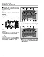
EXAMPLE
Step
: Top of MAG inlet port. Align 360
°
line of degree wheel
here
Step
: Find 65
°
on degree wheel and mark here
1. Closing mark
– Remove degree wheel.
– Position rotary valve on shaft splines to have
edges as close as possible to these marks with
the MAG piston at TDC.
NOTE :
Rotary valve is asymmetrical. There-
fore, try flipping it over then reinstall on
splines to obtain best installation position.
Apply BOMBARDIER injection oil on rotary valve
before reassembling rotary valve cover.
– Remove TDC gauge.
1,2, Rotary Valve Cover and Screw
Install O-ring and cover then torque screws to 20
N•m (15 lbf•pi) in a criss-cross sequence.
F01D3EA
2
1
65
°
1
1
2
'
Summary of Contents for Challenger 5896
Page 1: ......
Page 2: ......
Page 3: ...219 100 044 0 0 0 1996 Shop Manual 0 R ...
Page 152: ...Section 08 ELECTRICAL Sub Section 03 IGNITION SYSTEM 08 03 2 ELECTRICAL BOX Sportster F04H11S ...
Page 154: ...Section 08 ELECTRICAL Sub Section 03 IGNITION SYSTEM 08 03 4 ELECTRICAL BOX Speedster F04H26S ...
Page 251: ...Section 11 HULL DECK Sub Section 01 COMPONENTS 11 01 5 F04L3IS Loctite 242 ...
Page 274: ......


