Section 05
COOLING SYSTEM
Sub-Section 02
(CIRCUIT)
05-02-2
All Models
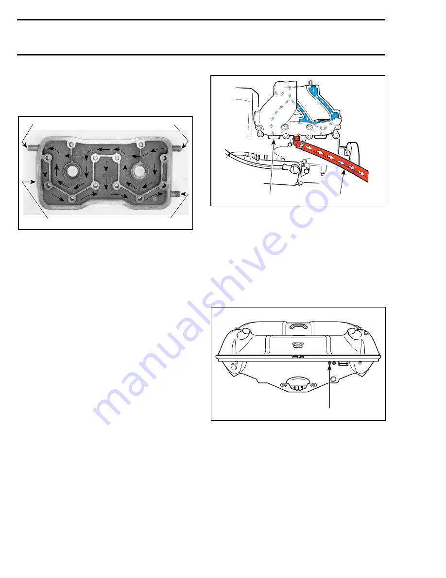
Fresh water from the jet pump enters the head
assembly, cooling the combustion chamber to
prevent detonation.
1. Cylinder head cover
2. Fresh water from jet pump
3. Water exiting head assembly to tuned pipe, exhaust manifold and
cylinders
4. Water from cylinder water jackets exiting engine
On Sportster / Speedster
, water flows out of cylin-
der head toward tuned pipe water jackets. A T-fitting
on the hose allows water to be injected with the
exhaust gases.
On Challenger
, water flows out of cylinder head
toward tuned pipe water jackets. The water to be
injected with the exhaust gases is controlled by
the water flow regulator valve as explained previ-
ously.
All Models
Water injected through the exhaust gases contin-
ues to flow out through the exhaust outlet. Water
in the tuned pipe water jackets continues to flow
through the exhaust manifold water jackets to-
ward the engine cylinder water jackets via pas-
sages below exhaust ports.
TYPICAL - SPORTSTER / SPEEDSTER
1. Water enters cylinder cooling jacket
2. Drain hose
The water continues to the engine cylinder head
and then goes out through the outlet fitting there.
No water enters crankcase.
For a minimum of back pressure in the exhaust,
engine water outlet hose is not connected to the
exhaust. It has its own fitting at the transom (the
same used for flushing the cooling system).
TYPICAL - SPORTSTER / CHALLENGER
1. Engine water outlet
F01E1LA
2
3
1
4
F01E0FA
1
2
F04L2YB
1
Summary of Contents for Challenger 5896
Page 1: ......
Page 2: ......
Page 3: ...219 100 044 0 0 0 1996 Shop Manual 0 R ...
Page 152: ...Section 08 ELECTRICAL Sub Section 03 IGNITION SYSTEM 08 03 2 ELECTRICAL BOX Sportster F04H11S ...
Page 154: ...Section 08 ELECTRICAL Sub Section 03 IGNITION SYSTEM 08 03 4 ELECTRICAL BOX Speedster F04H26S ...
Page 251: ...Section 11 HULL DECK Sub Section 01 COMPONENTS 11 01 5 F04L3IS Loctite 242 ...
Page 274: ......


