Section 06
FUEL SYSTEM
Sub-Section 03
(CARBURETORS)
06-03-9
CAUTION : If boat is out of water, water
must be supplied to cool engine with a
garden hose.
Turning screw clockwise leans mixture and turn-
ing screw counterclockwise enriches mixture.
Turn low-speed mixture screw so that engine
reaches the most suitable idle and runs smoothly.
Make sure engine reacts quickly when pushing
throttle lever(s).
Both low-speed mixture screws must be adjusted
exactly the same way. Never adjust screws more
than 1/4 turn at a time.
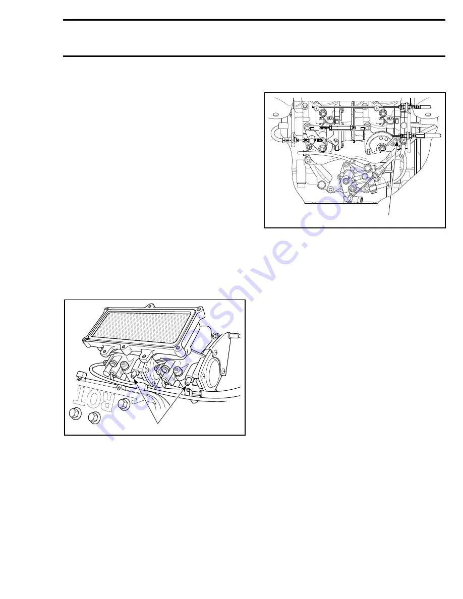
16, High-Speed Mixture Screw
The high-speed mixture screw is sealed with a
plastic cap that allows an adjustment of 1/4 turn.
NOTE :
Turning screw 1/4 turn counterclock-
wise enriches mixture and turning screw
clockwise leans mixture.
CAUTION : Do not attempt to adjust high-
speed mixture screw. Severe engine dam-
age can occur.
TYPICAL
1. High speed screws
15, Idle Speed Screw
717 ENGINE SHOWN
1. Idle speed screw
Turning screw clockwise increases engine idle
speed and turning screw counterclockwise de-
creases engine idle speed.
NOTE :
There is only one idle speed screw
for both carburetors. It is located on the
MAG side carburetor.
Connect an induction-type tachometer (P / N 295
000 100) on spark plug cable of magneto side to
measure engine speed.
NOTE :
To adjust idle speed, ensure flame
arrester and air intake silencer are installed.
Spray a soapy solution on wear ring of jet pump.
Start engine and bring to normal operating tem-
perature.
CAUTION : If boat is out of water, water
must be supplied to cool engine with a
garden hose.
Turn screw so that engine idles at 1500 RPM (in
water). If boat is out of water, idle speed should
be 3000 RPM.
WARNING : Make sure idle speed screw
contacts stopper when throttle lever is ful-
ly pulled back. Otherwise, readjust throttle ca-
ble.
FUEL SYSTEM PRESSURIZATION
WARNING : Whenever doing any type of
repair on jet boat or if any components of
the fuel system are disconnected, a pressure
test must be done before starting engine and /
or releasing jet boat to customer.
-
'
-
F01F2Q A
1
F01F07C
1
'
'
-
;
;
Summary of Contents for Challenger 5896
Page 1: ......
Page 2: ......
Page 3: ...219 100 044 0 0 0 1996 Shop Manual 0 R ...
Page 152: ...Section 08 ELECTRICAL Sub Section 03 IGNITION SYSTEM 08 03 2 ELECTRICAL BOX Sportster F04H11S ...
Page 154: ...Section 08 ELECTRICAL Sub Section 03 IGNITION SYSTEM 08 03 4 ELECTRICAL BOX Speedster F04H26S ...
Page 251: ...Section 11 HULL DECK Sub Section 01 COMPONENTS 11 01 5 F04L3IS Loctite 242 ...
Page 274: ......


