Section 08
ELECTRICAL
Sub-Section 02
(MAGNETO SYSTEM)
08-02-3
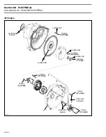
3, Charging System Generator Coil
To replace :
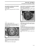
– Heat the armature plate to 93
°
C (200
°
F) around
the screw holes to break the threadlocker
bond.
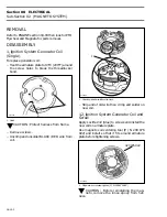
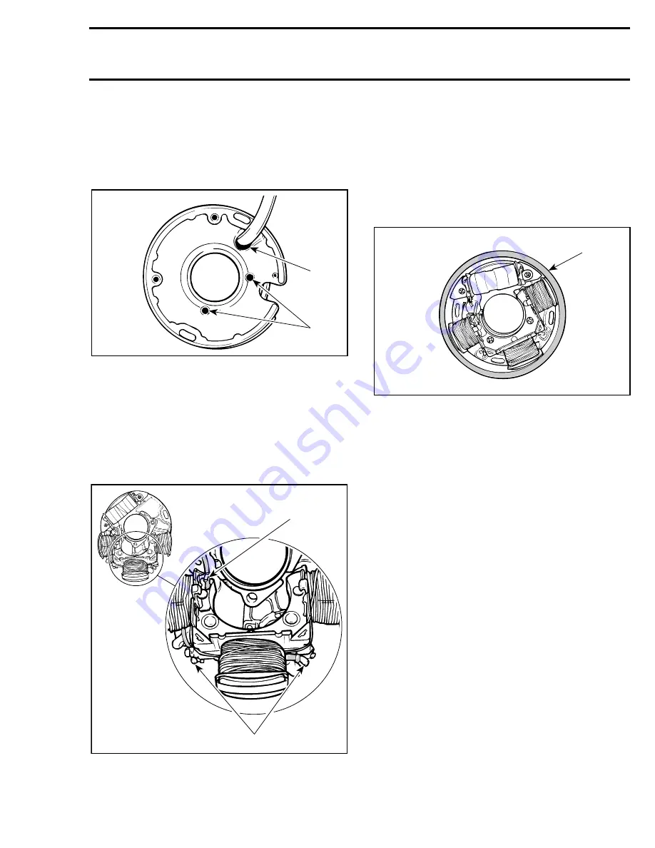
1. Heat
CAUTION : Protect harness from flame.
– Remove screws.
– Uncrimp and unsolder YELLOW and YELLOW /
BLACK wires from coil.
– Uncrimp and unsolder ground wire (BLACK)
from coil core.
1. Uncrimp and unsolder ground wire (BLACK) here
2. Uncrimp and unsolder YELLOW and YELLOW / BLACK wires
here
– Position new coil, crimp and solder all wires.
3,4, Charging System Generator Coil
and Screw
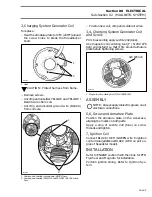
Prior to assembly, apply Loctite 242 (blue).
Use magneto coil centering tool (P / N 290 876
922) and install it so that it fits around armature
plate before tightening screws.
1. Magneto coil centering tool (P
/
N 290 876 922)
ASSEMBLY
NOTE :
Always apply dielectric grease on all
electrical connections.
5,6, Screw and Armature Plate
Position the armature plate on the crankcase,
aligning the marks on both parts.
Apply a drop of Loctite 242 (blue) on screw
threads and tighten.
7, Ignition Coil
Connect BLACK / RED
/
GREEN wire to ignition
coil terminal (additional BLACK
/
RED on port en-
gine of Speedster model).
INSTALLATION
Refer to ENGINE section 04-03 then look for
PTO
Flywheel and Magneto
for installation.
Perform ignition timing. Refer to
Ignition Sys-
tem
.
A01C2JA
2
1
-
A25E0SA
1
2
A25E0RD
420 8769 22
'
Summary of Contents for Challenger 5896
Page 1: ......
Page 2: ......
Page 3: ...219 100 044 0 0 0 1996 Shop Manual 0 R ...
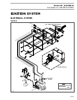
Page 152: ...Section 08 ELECTRICAL Sub Section 03 IGNITION SYSTEM 08 03 2 ELECTRICAL BOX Sportster F04H11S ...
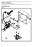
Page 154: ...Section 08 ELECTRICAL Sub Section 03 IGNITION SYSTEM 08 03 4 ELECTRICAL BOX Speedster F04H26S ...
Page 251: ...Section 11 HULL DECK Sub Section 01 COMPONENTS 11 01 5 F04L3IS Loctite 242 ...
Page 274: ......


