Section 08
ELECTRICAL
Sub-Section 03
(IGNITION SYSTEM)
08-03-6
Magneto
/
Ignition Coil Output Tests
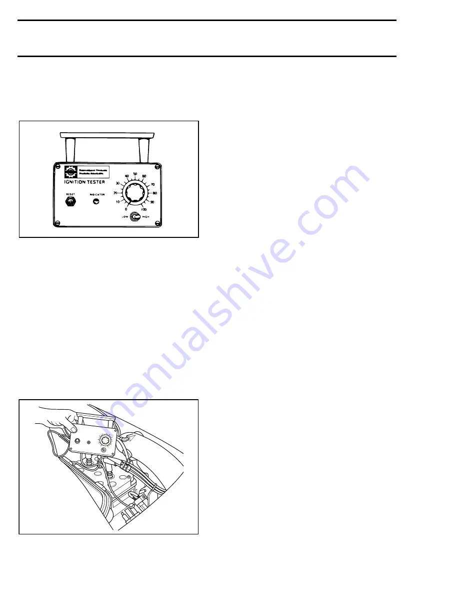
These items can be easily checked with Bombar-
dier ignition tester (P
/
N 295 000 008) and the 4-
pin magneto test harness (P / 295 000 131).
For more information concerning operation and
maintenance of the tester, refer to its instruction
manual.
USE OF BOMBARDIER IGNITION TESTER
This tester can verify generating coil, ignition
module, ignition coil and battery charging coil.
Always make sure that tester batteries are in
good condition.
TEST CONDITION
All tests are performed on boat at cranking speed
with spark plugs installed.
Always proceed in the following order :
1. Connect tester
P
and
N
clip leads as indicated
for each specific test.
TYPICAL
2. Follow test procedure sequence.
3. Install cap over safety lanyard post and depress
starting button until light turns on, or otherwise,
for a maximum of 5 seconds.
4. If engine starts when performing some test, al-
low it to idle while observing indicator. Then,
shut engine off.
5. After every test that lights the indicator lamp,
RESET the indicator circuit by depressing the
reset button.
ANALYSIS OFf TEST RESULT
Indicator Lamp Lights at Specific Setting
Output is as specified. Test results should repeat
3 times. If readings do not repeat, output is erratic
and cause should be investigated (loose connec-
tions or components, etc.).
Indicator Lamp Lights at Lower Setting
This indicates that the output is less than that de-
signed to operate in a satisfactory manner. How-
ever, before coming to the conclusion of a faulty
condition be certain that correct engine cranking
conditions were met before condemning the test-
ed part.
Indicator Lamp Does Not Light
One component is defective. Proceed as instruct-
ed to find defective component.
Intermittent Ignition Problems
In dealing with intermittent problems there is no
easy diagnosis. For example, problems that occur
only at normal engine operating temperature have
to be tested under similar conditions.
In most cases of temperature and
/
or vibration
failure, only parts replacement can solve the prob-
lem as most of these failures return to normal
when engine is not running.
Multiple Problems
There is always the possibility of more than one
faulty part. If after a component has been re-
placed, the problem still persists, carefully repeat
the complete test procedure to find the other
faulty part.
A00E0EA
IGNITION TESTER
100
90
80
70
60
50
40
30
20
10
0
ELECTRO-SPECIAL
TIES, INC.
LOW
HIGH
F01H2UA
Summary of Contents for Challenger 5896
Page 1: ......
Page 2: ......
Page 3: ...219 100 044 0 0 0 1996 Shop Manual 0 R ...
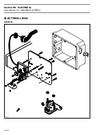
Page 152: ...Section 08 ELECTRICAL Sub Section 03 IGNITION SYSTEM 08 03 2 ELECTRICAL BOX Sportster F04H11S ...
Page 154: ...Section 08 ELECTRICAL Sub Section 03 IGNITION SYSTEM 08 03 4 ELECTRICAL BOX Speedster F04H26S ...
Page 251: ...Section 11 HULL DECK Sub Section 01 COMPONENTS 11 01 5 F04L3IS Loctite 242 ...
Page 274: ......


