Section 08
ELECTRICAL
Sub-Section 03
(IGNITION SYSTEM)
08-03-14
DYNAMIC TEST
Test can be performed with either the Bombardier
ignition tester (P / N 295 000 008) OR the KOWA
ignition coil tester (typical), available from after
market tool / equipment suppliers.
Testing with the Bombardier Ignition Tester
For more information how to perform the test and
interpret the results, refer to ‘’USE OF BOMBAR-
DIER IGNITION TESTER’’ earlyer in the
717 en-
gine
section.
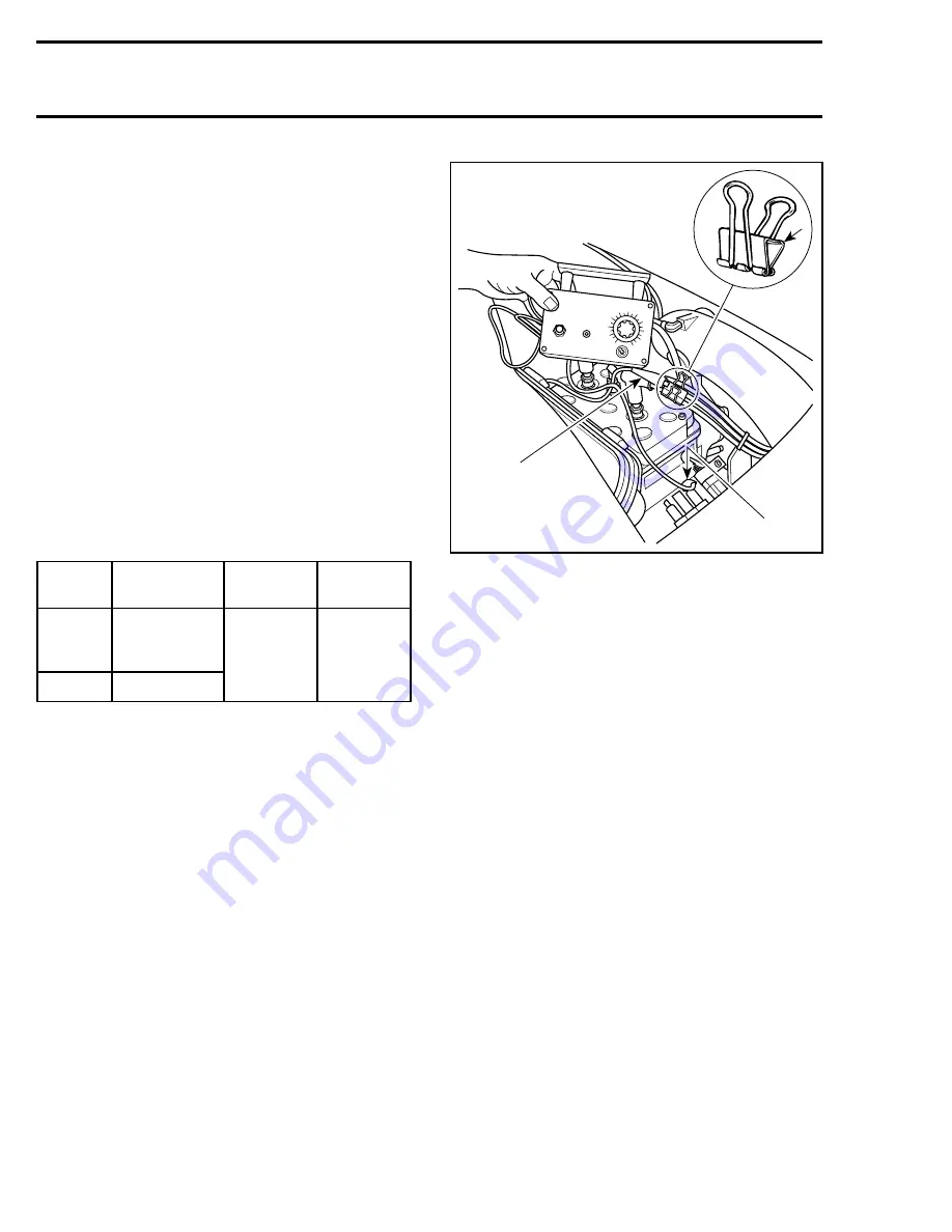
A paper clip of approximately 20 mm (3/4 in) will
be used as a test adapter for the following test.
1. Install the test adapter to spark plug cable close
to MAG side spark plug. Unplug magneto con-
nector at engine. Connect the 6-pin magneto
test harness (P / N 295 000 136) between the
unplugged connectors.
2. Connect tester wires then set switch and dial
as follows :
TYPICAL
1. Paper clip
2. P lead to GROUND
3. N lead on spark plug cable
3. Start engine and observe indicator.
NOTE :
If engine starts, allow it to idle while
observing indicator. Then, shut engine off.
4. Push reset button and repeat step 3 twice.
RESULTS :
a.
Indicator lamp lights
:
Ignition coil is OK.
b.
Indicator lamp does not light on one or
both cylinder(s)
:
Repeat the test 3 times to
get conclusive results. Ignition coil is faulty.
Replace it.
Testing with the KOWA ignition coil tester
WARNING : Do NOT use coil tester on
metal work bench. Follow manufacturer
instructions.
1. With ignition coil removed from craft, discon-
nect spark plug caps from high tension leads.
2. Hook high tension leads from tester to ignition
coil high tension leads.
3. Connect 2 smaller tester leads to primary of ig-
nition coil.
Tester
wires
Component
wires
Tester switch
position
Tester dial
position
N
Tester adapter
(paper clip) on
spark plug cable
LOW
35
P
Engine ground
IGNITION TESTER
100
90
80
70
60
50
40
30
20
10
0
ELECTRO-SPECIAL
TIES, INC.
LOW
HIGH
3
F01H5MA
2
1
'
;
Summary of Contents for Challenger 5896
Page 1: ......
Page 2: ......
Page 3: ...219 100 044 0 0 0 1996 Shop Manual 0 R ...
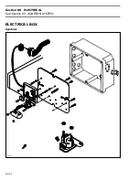
Page 152: ...Section 08 ELECTRICAL Sub Section 03 IGNITION SYSTEM 08 03 2 ELECTRICAL BOX Sportster F04H11S ...
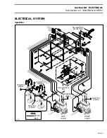
Page 154: ...Section 08 ELECTRICAL Sub Section 03 IGNITION SYSTEM 08 03 4 ELECTRICAL BOX Speedster F04H26S ...
Page 251: ...Section 11 HULL DECK Sub Section 01 COMPONENTS 11 01 5 F04L3IS Loctite 242 ...
Page 274: ......

