Section 08
ELECTRICAL
Sub-Section 03
(IGNITION SYSTEM)
08-03-15
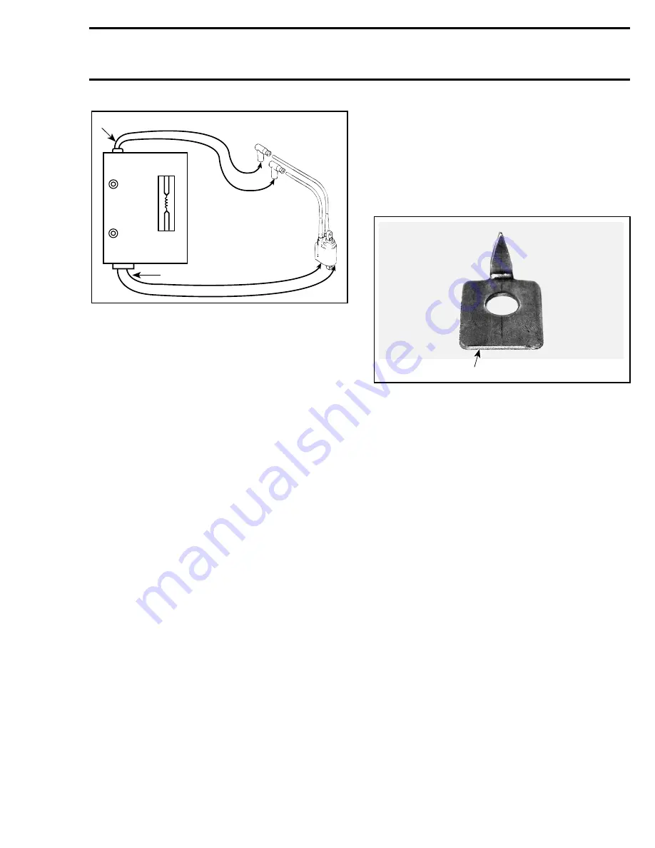
TYPICAL
1. Leads to secondary
2. Leads to primary
4. Turn power switch to 12 volts and you should
observe spark jumping at a predetermined gap
of 7 to 8 mm (.276 to .311 in).
If there is no spark, if it is weak or intermittent, the
coil is defective and should be replaced.
5. Observe tester operating time recommenda-
tions, usually about 5 minutes per coil is suffi-
cient.
IGNITION TIMING, 787 ENGINE
Overview
Normally ignition timing adjustment should not be
required. It has been set at factory and it should
remain correctly adjusted since every part is fixed
and is not adjustable. The only time the ignition
timing might have to be changed would be when
replacing the crankshaft, the magneto flywheel,
the trigger coil, the Nippondenso DC-CDI module
or the MPEM. If the ignition timing is found incor-
rect, you should first check for proper crankshaft
alignment. This might be the indication of a twist-
ed crankshaft.
With this new CDI system, the ignition timing can
be checked with either the engine hot or cold. Be-
sides the
ignition timing is to be checked at
3500 RPM
with the timing light.
Within 3000 and 4000 RPM, the spark advance
does not change. So when checking timing at
3500 RPM, a change in engine speed within
±
500
RPM will not affect the timing mark when
checked with the timing light.
Ignition Timing Procedure
STATIC TEST
1. To install the new timing mark pointer tool, first
remove PTO flywheel guard. Then remove mid-
dle screw securing the engine to the rear cross-
over motor mount. Reinstall screw with timing
mark pointer tool attached.
1. Timing mark pointer tool (P / N 295 000 135)
2. Install a TDC gauge in MAG side spark plug
hole. Rotate PTO flywheel until piston is at top
dead center.
3. From this point, rotate flywheel clockwise
(when facing it) until piston is at 3.38 mm (.133
in) before top dead center.
4. Scribe a mark on PTO flywheel aligned with
timing mark pointer tool.
5. Remove TDC gauge, reinstall spark plug and
connect wire.
DYNAMIC TEST
1. Connect an induction-type tachometer (P / N
295 000 100) to spark plug wire.
2. Check ignition timing using a stroboscopic tim-
ing light connected to the MAG side spark plug
cable. Rev the engine to 3500 RPM and point
beam of timing light straight in line with timing
mark pointer.
CAUTION : If engine is to be run more
than a few seconds, connect a garden
hose and supply water to the engine to proper-
ly cool it.
NOTE :
If mark on PTO flywheel is perfectly
aligned with timing mark pointer, no adjust-
ment is required. If it is not the case, refer to the
following procedure.
ON
OFF
12 V
6 V
F01H55A
1
2
F01H54A
1
-
'
Summary of Contents for Challenger 5896
Page 1: ......
Page 2: ......
Page 3: ...219 100 044 0 0 0 1996 Shop Manual 0 R ...
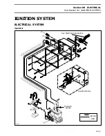
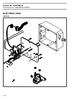
Page 152: ...Section 08 ELECTRICAL Sub Section 03 IGNITION SYSTEM 08 03 2 ELECTRICAL BOX Sportster F04H11S ...
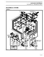
Page 154: ...Section 08 ELECTRICAL Sub Section 03 IGNITION SYSTEM 08 03 4 ELECTRICAL BOX Speedster F04H26S ...
Page 251: ...Section 11 HULL DECK Sub Section 01 COMPONENTS 11 01 5 F04L3IS Loctite 242 ...
Page 274: ......

