Section 09
PROPULSION AND DRIVE SYSTEMS
Sub-Section 01
(PROPULSION AND DRIVE SYSTEMS)
09-01-11
A. 22 mm (.865 in) dia.
B. 28 mm (1.115 in) dia.
C. 90 mm (3-1/2 in)
D. 345 mm (13-1/2 in)
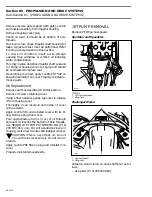
Insert pusher into one bearing then push tool us-
ing a arbor press until bearings are out. However,
care should be taken not to damage bearing jour-
nals.
1. Press bearings out
CLEANING
NOTE :
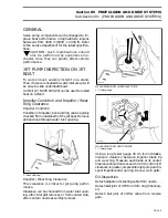
Cooling supply fitting can be re-
moved to ease cleaning of impeller housing
mating surface (not required on Speedster).
Sealant can be removed with a steel brush (disc)
mounted on a drill or a scraper.
Bombardier stripper (P / N 295 500 110) can be
used to remove remaining sealant. Carefully apply
on mating surface taking care not to exceed this
area because paint will be damaged. Let product
dissolve sealant then scrape it.
Properly clean all threads.
Discard all O-rings and clean parts in a solvent.
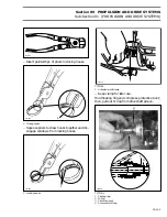
Carefully check water passages (Cooling system)
and oil passages. Blow low pressure compressed
air through them and make sure they are not
clogged.
1. Water passages
2. Oil passages
PARTS INSPECTION
33,34,35,36, Protective, Boot, Carbon
Ring, O-Ring and Floating Ring
Inspect carbon ring for wear at the inside and at
the flange where it contacts the floating ring.
Inspect the floating ring flange where it contacts
the carbon ring.
Inspect O-rings and protective boot for cracks,
cuts etc.
Replace parts as necessary.
19,23,24, Impeller, PTO Flywheel and
Drive Shaft
Visually inspect drive shaft splines, impeller and
PTO flywheel. Check for wear or deformation. Re-
new any damaged part.
NOTE :
If PTO flywheel splines are very
worn, a pipe wrench can be used to remove
PTO flywheel instead of special tool (P / N 295
000 001). Refer to ENGINE 04-03 then look for
PTO flywheel and magneto.
Inspect drive shaft protector tube condition.
Check inside of tube and its retaining tabs. Re-
place tube as necessary.
F01J11A
A
B
C
D
D
1
F01J12B
'
F01J13B
1
2
'
Summary of Contents for Challenger 5896
Page 1: ......
Page 2: ......
Page 3: ...219 100 044 0 0 0 1996 Shop Manual 0 R ...
Page 152: ...Section 08 ELECTRICAL Sub Section 03 IGNITION SYSTEM 08 03 2 ELECTRICAL BOX Sportster F04H11S ...
Page 154: ...Section 08 ELECTRICAL Sub Section 03 IGNITION SYSTEM 08 03 4 ELECTRICAL BOX Speedster F04H26S ...
Page 251: ...Section 11 HULL DECK Sub Section 01 COMPONENTS 11 01 5 F04L3IS Loctite 242 ...
Page 274: ......


