Section 09
PROPULSION AND DRIVE SYSTEMS
Sub-Section 01
(PROPULSION AND DRIVE SYSTEMS)
09-01-16
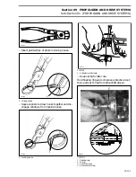
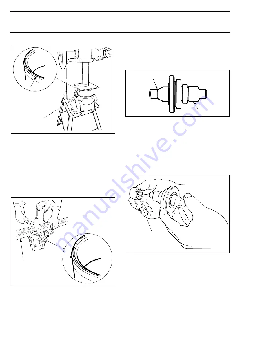
1. Seal lip
2. Press wear ring
If a press is not readily available, a piece of wood
such as a 2 x 4 x 12 in. long, can be used.
Manually engage ring in housing making sure it is
equally inserted all around. Place wood piece over
ring. Using a hammer, strike on wood to push
ring. Strike one side then rotate wood piece about
90
°
and strike again. Frequently rotate wood
piece so that ring slides equally all around until it
seats into bottom of housing.
1. Piece of wood
2. Seal lip here
3. Wear ring
21,22, Seal and Needle Bearing
Bearings and seal will be properly installed in
housing using bearing / seal installer tool (P / N
295 000 107).
BEARING
/
SEAL INSTALLER TOOL
1. Seal end
2. Bearing end
Stamped end of bearings (showing identification
markings) must be located toward outside of
housing.
Properly insert bearing on tool. Using an arbor
press only, push tool until tool flange contacts
housing. Proceed the same way for both bear-
ings.
1. Stamped end this side
CAUTION : Never hammer the bearing
into its housing.
F01J5DA
1
2
F01J5EA
1
3
2
F01J4KA
2
1
F01J1HA
1
-
Summary of Contents for Challenger 5896
Page 1: ......
Page 2: ......
Page 3: ...219 100 044 0 0 0 1996 Shop Manual 0 R ...
Page 152: ...Section 08 ELECTRICAL Sub Section 03 IGNITION SYSTEM 08 03 2 ELECTRICAL BOX Sportster F04H11S ...
Page 154: ...Section 08 ELECTRICAL Sub Section 03 IGNITION SYSTEM 08 03 4 ELECTRICAL BOX Speedster F04H26S ...
Page 251: ...Section 11 HULL DECK Sub Section 01 COMPONENTS 11 01 5 F04L3IS Loctite 242 ...
Page 274: ......

