Section 10
STEERING SYSTEM
Sub-Section 01
(STEERING SYSTEM)
10-01-4
Installation
Reinstall removed parts and pay attention to the
following
:
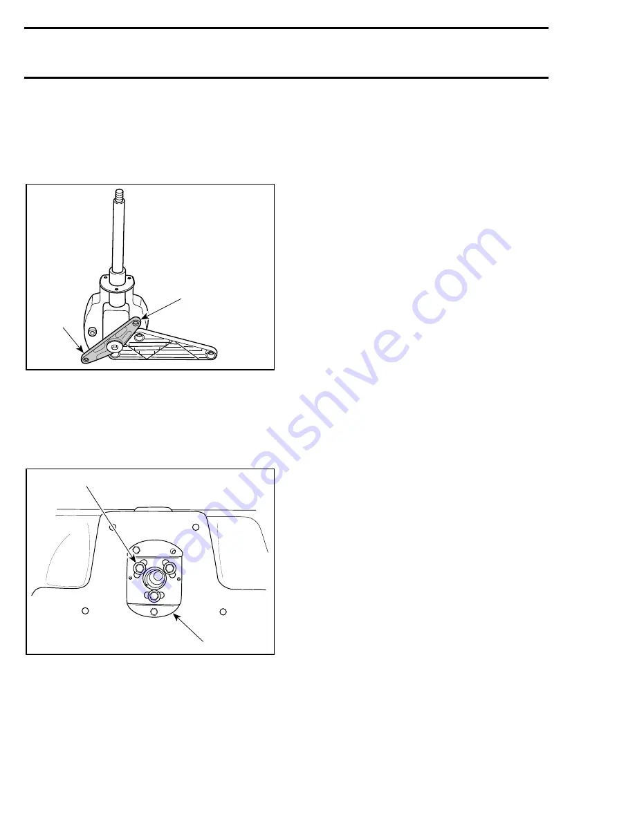
Prior to installing steering helm to boat, position
helm arm as shown.
1. Correct position
2. Helm arm
– When installing steering helm to boat, position
screws no.
9 as required in slots on mounting
plate to keep space between helm
/
cable and
body. Centering screws in slots is a good start-
ing point.
1. Screw centered in slot
2. Mounting plate
– Torque screws as indicated in exploded view.
– Ensure to install Woodruff key.
– Torque lock nut of steering as indicated in ex-
ploded view.
– Proceed with steering alignment. Refer to
ALIGNMENT, section 10-02.
F04K09A
1
2
F04K06A
1
2
Summary of Contents for Challenger 5896
Page 1: ......
Page 2: ......
Page 3: ...219 100 044 0 0 0 1996 Shop Manual 0 R ...
Page 152: ...Section 08 ELECTRICAL Sub Section 03 IGNITION SYSTEM 08 03 2 ELECTRICAL BOX Sportster F04H11S ...
Page 154: ...Section 08 ELECTRICAL Sub Section 03 IGNITION SYSTEM 08 03 4 ELECTRICAL BOX Speedster F04H26S ...
Page 251: ...Section 11 HULL DECK Sub Section 01 COMPONENTS 11 01 5 F04L3IS Loctite 242 ...
Page 274: ......


