Section 10
STEERING SYSTEM
Sub-Section 03
(THROTTLE / SHIFTER / VTS CONTROLLER)
10-03-2
Speedster
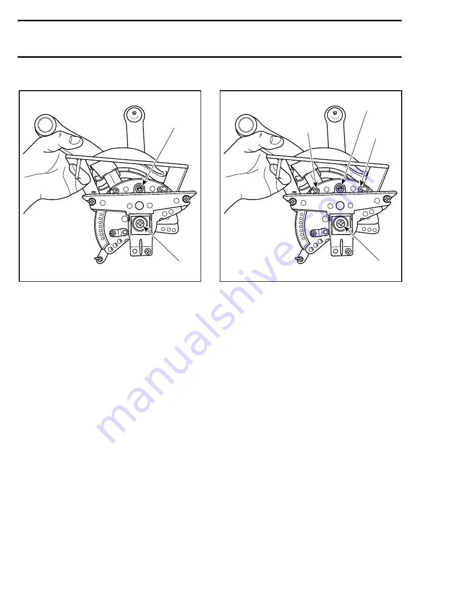
1. Set screw of shifter and starboard throttle (outer lever)
2. Set screw of port throttle (inner lever)
To adjust shifter friction, turn set screw that is on
the same side as shifter lever.
To adjust starboard throttle lever (outer lever), turn
set screw on the same side as its lever.
To adjust port throttle lever (inner lever), turn set
screw on center of pivot point of lever.
Ensure that both throttle levers have the same
friction.
Challenger
TYPICAL
1. Set screw of shifter and VTS
2. Set screw of throttle
3. Screws and springs for “ratchetting” effect of the VTS lever
To adjust shifter friction, turn set screw that is on
the same side as shifter lever.
The set screw of the VTS lever has very little ef-
fect because of the “ratchetting” mechanism.
To adjust throttle lever turn set screw on center of
pivot point of lever.
The “ratchetting” effect for the VTS lever is pro-
vided by 2 spring-loaded steel balls (see illustra-
tion). If the “ratchetting” is not felt, check those
components.
Shifter Lock Adjustment
All Models
The locking action can be adjusted. The positions
Forward
/
Neutral
/
Reverse are “notched” by
means of a steel ball pushed by a spring against a
notch on shifter plate.
Turning the set screw clockwise will increase
spring pressure and therefore “hardens” shifter
lock action. Conversely turning screw counter-
clockwise “softens” lock action.
The set screw is located on the same side as
shifter lever.
1
F04K07A
2
1
F04K07B
2
3
3
Summary of Contents for Challenger 5896
Page 1: ......
Page 2: ......
Page 3: ...219 100 044 0 0 0 1996 Shop Manual 0 R ...
Page 152: ...Section 08 ELECTRICAL Sub Section 03 IGNITION SYSTEM 08 03 2 ELECTRICAL BOX Sportster F04H11S ...
Page 154: ...Section 08 ELECTRICAL Sub Section 03 IGNITION SYSTEM 08 03 4 ELECTRICAL BOX Speedster F04H26S ...
Page 251: ...Section 11 HULL DECK Sub Section 01 COMPONENTS 11 01 5 F04L3IS Loctite 242 ...
Page 274: ......


