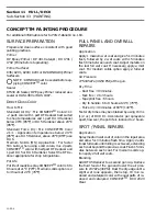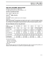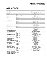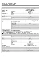
Section 11
HULL / DECK
Sub-Section 01
(COMPONENTS)
11-01-8
DRAIN REPLACEMENT
Bilge Pump Drain
• Disconnect drain tube from transom fitting.
• Cut locking ties all along drain tube from tran-
som toward bilge pump.
• Disconnect drain tube from bilge pump and re-
move tube.
• Cut new tube to proper length.
• Reconnect tube at each end and resecure tube
with locking ties.
• Ensure tube does not leak in bilge.
Deck Drain
• Disconnect drain tube from transom fitting.
• Cut locking ties all along drain tube from tran-
som toward deck storage compartment.
• Remove throttle
/
shifter controller to gain ac-
cess.
• From the controller opening, disconnect drain
tube from deck fitting.
• Cut new tube to proper length.
• Reconnect tube at each end and resecure with
locking ties.
• Ensure tube does not leak in bilge.
Scupper Valve
Check rubber valve condition (cracks, tears etc.),
and operation (should remain closed or near to
closed). Replace as necessary.
If scupper valve cover has been removed, ensure
to position tabs on top at reinstallation. See illus-
tration above.
SEAT REMOVAL
/
INSTALLATION
NOTE :
A screwdriver may be used carefully
to pry seat
/
backrest out.
CAUTION : Ensure to protect body prior
to prying.
Whenever removing seat and
/
or backrest, al-
ways replace darts prior to reinstalling.
Rear Seat
Carefully pry sides of seat to release the darts.
The 4 retaining screws can be reached from en-
gine compartment underneath seat.
Rear Backrest
The 4 rear retaining screws can be reached from
engine compartment. Remove electrical box to
reach starboard retaining screw.
The starboard (RH) retaining screw can be
reached by removing throttle
/
shifter controller.
The port (LH) retaining screw can be reached by
removing the cup holder.
Apply Loctite 242 (blue) on screw threads at as-
sembly.
Front Seat
Carefully pry seat up to release the darts.
Front Backrest
Carefully pry bottom of backrest to release the
darts. Lift backrest to remove.
Spotter Seat
Challenger
BACKREST
The backrest is retained by 3 screws which can be
accessed by lifting the cooler cover.
SEAT
Start to pry out darts in the corners of the seat
below the backrest area. Lift the front portion of
the seat to release the retaining bracket and at the
same time, pull the seat out.
'
-
Summary of Contents for Challenger 5896
Page 1: ......
Page 2: ......
Page 3: ...219 100 044 0 0 0 1996 Shop Manual 0 R ...
Page 152: ...Section 08 ELECTRICAL Sub Section 03 IGNITION SYSTEM 08 03 2 ELECTRICAL BOX Sportster F04H11S ...
Page 154: ...Section 08 ELECTRICAL Sub Section 03 IGNITION SYSTEM 08 03 4 ELECTRICAL BOX Speedster F04H26S ...
Page 251: ...Section 11 HULL DECK Sub Section 01 COMPONENTS 11 01 5 F04L3IS Loctite 242 ...
Page 274: ......


