Section 04
ENGINE
Sub-Section 01
(REMOVAL AND INSTALLATION)
04-01-7
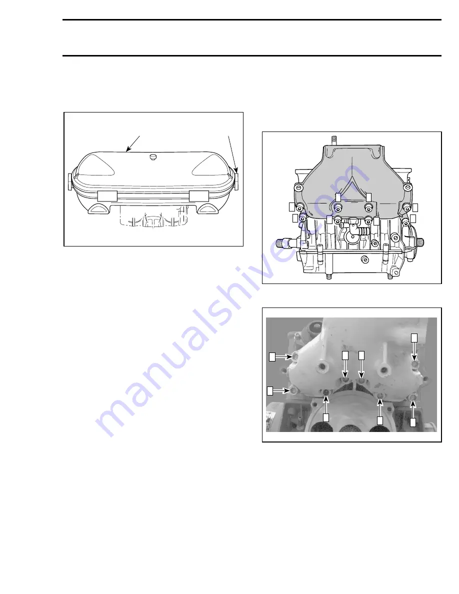
Air Intake Silencer Removal
Unlock retaining slides holding air intake silencer
cover and remove cover.
TYPICAL
1. Air intake silencer cover
2. Unlock
Remove flame arrester retainer screws ; then, re-
move air intake silencer base.
Flame Arrester Base Removal
Remove screws holding flame arrester base sup-
port to the cylinder head cover.
Remove flame arrester.
Remove screws from flame arrester base then
withdraw base.
CLEANING
Wipe off any spillage in bilge. Clean with a bilge
cleaner.
Discard all gaskets and O-rings.
Clean external parts of engine.
INSTALLATION
Installation of engine in jet boat is essentially the
reverse of removal procedures. However pay par-
ticular attention to the following.
7,18, Exhaust Manifold and Screw
Apply Loctite 242 (blue) on screw threads. (
717
engine)
.
Apply Loctite 515 on screw threads (
787 engine
).
Install and torque exhaust manifold screws to 12
N•m (9 lbf•ft) as per following illustrated se-
quence. Repeat the procedure, retightening
screws to 24 N•m (17 lbf•ft).
717 Engine
787 Engine
Make sure to install sealing ring on tuned pipe
cone.
F01F2OA
1
2
F01D59A
1
3
5
8
2
4
7
6
F01D82A
3
1
7
6
4
8
2
5
Summary of Contents for Challenger 5896
Page 1: ......
Page 2: ......
Page 3: ...219 100 044 0 0 0 1996 Shop Manual 0 R ...
Page 152: ...Section 08 ELECTRICAL Sub Section 03 IGNITION SYSTEM 08 03 2 ELECTRICAL BOX Sportster F04H11S ...
Page 154: ...Section 08 ELECTRICAL Sub Section 03 IGNITION SYSTEM 08 03 4 ELECTRICAL BOX Speedster F04H26S ...
Page 251: ...Section 11 HULL DECK Sub Section 01 COMPONENTS 11 01 5 F04L3IS Loctite 242 ...
Page 274: ......


