Section 04
ENGINE
Sub-Section 02
(TOP END)
04-02-4
– The needles, thrust washers and the expansion
sleeve remain in the connecting rod bore and
may be used again.
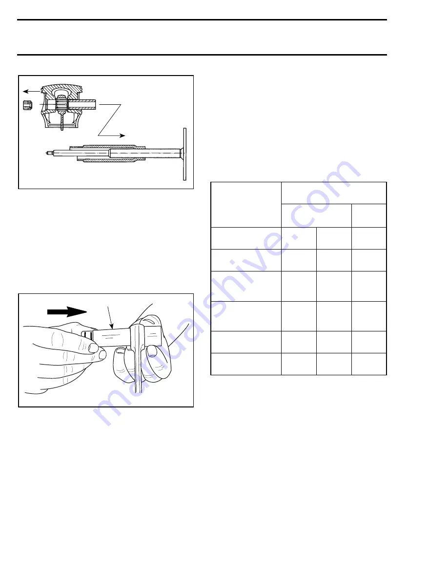
To remove rollers with the thrust washers from
the connecting rod bore, push them together with
the expansion sleeve into the locating sleeve (P /
N 290 877 180) using any suitable 23 mm (.905 in)
diameter pusher.
CAUTION : Recover rollers, make sure
that 34 rollers are found for each piston.
1. Pusher 23 mm (.905 in)
CLEANING
Discard all gaskets and O-rings.
Clean all metal components in a solvent.
Clean water passages and make sure they are not
clogged.
Remove carbon deposits from cylinder exhaust
port, cylinder head and piston dome.
Clean piston ring grooves with a groove cleaner
tool, or a piece of broken ring.
INSPECTION
Visually inspect all parts for corrosion damage.
Inspect piston for damage. Light scratches can be
sanded with a fine sand paper.
Inspect plane surfaces for warpage. Small defor-
mation can be corrected by grinding surface with
a fine sand paper. Install sand paper on a surface
plate and rub part against oiled sand paper.
The inspection of engine top end should include
the following measurements.
NOTE :
Replacement cylinder sleeves are
available if necessary. Consult a specialized
shop for installation.
NOTE :
0.25 annd rings available if neces-
sary.
F01D2YA
-
A21C04A
1
ENGINE
MEASUREMENT
TOLERANCES
(ALL ENGINES)
NEW PARTS
WEAR
LIMIT
(min.)
(max.)
Cylinder Taper
N.A.
N.A.
0.1 mm
(.004 in)
Cylinder Out
of Round
N.A.
N.A.
0.08 mm
(.003 in)
Piston / Cylinder
Clearance for
717 Engine
0.06 mm
(.0024 in)
0.08 mm
(.0031 in)
0.2 mm
(.008 in)
Piston / Cylinder
Clearance for
787 Engine
0.10 mm
(.0024 in)
0.06 mm
(.0024 in)
0.06 mm
(.0024 in)
Ring / Piston
Groove Clearance
0.06 mm
(.0039 in)
0.12 mm
(.0047 in)
0.15 mm
(.006 in)
Ring End Gap
0.25 mm
(.010 in)
0.06 mm
(.016 in)
0.06 mm
(.039 in)
'
'
Summary of Contents for Challenger 5896
Page 1: ......
Page 2: ......
Page 3: ...219 100 044 0 0 0 1996 Shop Manual 0 R ...
Page 152: ...Section 08 ELECTRICAL Sub Section 03 IGNITION SYSTEM 08 03 2 ELECTRICAL BOX Sportster F04H11S ...
Page 154: ...Section 08 ELECTRICAL Sub Section 03 IGNITION SYSTEM 08 03 4 ELECTRICAL BOX Speedster F04H26S ...
Page 251: ...Section 11 HULL DECK Sub Section 01 COMPONENTS 11 01 5 F04L3IS Loctite 242 ...
Page 274: ......


