Section 04
ENGINE
Sub-Section 05
(ROTARY VALVE)
04-05-2
GENERAL
The following verification procedures such as
clearance of rotary valve cover or rotary valve
shaft gear backlash can be performed without re-
moving engine from boat. Refer to INSPECTION
further in this section.
However engine must be removed from boat to
work on rotary valve shaft / components. Refer to
REMOVAL AND INSTALLATION 04-01 for proce-
dures.
Bottom end must be opened to remove rotary
valve shaft.
DISASSEMBLY
1,2, Rotary Valve Cover and Screw
Unscrew 4 retaining screws and withdraw rotary
valve cover and valve.
NOTE :
It is necessary to withdraw carbure-
tors prior removing rotary valve cover. Refer
to FUEL SYSTEM 06-03 then refer to
Carburetor
Removal
.
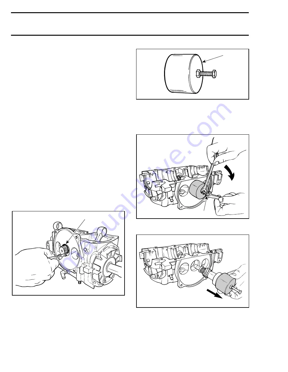
3,4, Rotary Valve Shaft and Snap Ring
To remove rotary valve shaft assembly from
crankcase, first remove snap ring from crankcase.
TYPICAL
1. Removing snap ring
CAUTION : Bottom end must be opened
to remove rotary valve shaft.
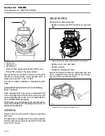
To remove rotary valve shaft, use puller (P / N 290
876 487 for
717 engine
and 290 876 488 for
787
engine
).
1. Rotary valve shaft remover
Place puller over rotary valve shaft end and screw
on puller bolt into shaft. While retaining bolt with
a wrench, turn puller nut CLOCKWISE until shaft
comes out.
TYPICAL
1. Hold bolt
TYPICAL
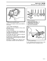
5,6, Circlip and Spring Seat
If it is necessary to disassemble components of
rotary valve shaft assembly, use seat to compress
spring and remove circlips.
'
F01D22A
1
-
F01D23C
1
F01D61A
1
F01D27A
Summary of Contents for Challenger 5896
Page 1: ......
Page 2: ......
Page 3: ...219 100 044 0 0 0 1996 Shop Manual 0 R ...
Page 152: ...Section 08 ELECTRICAL Sub Section 03 IGNITION SYSTEM 08 03 2 ELECTRICAL BOX Sportster F04H11S ...
Page 154: ...Section 08 ELECTRICAL Sub Section 03 IGNITION SYSTEM 08 03 4 ELECTRICAL BOX Speedster F04H26S ...
Page 251: ...Section 11 HULL DECK Sub Section 01 COMPONENTS 11 01 5 F04L3IS Loctite 242 ...
Page 274: ......


