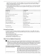
External Installation Water Connections
Pipe sizes to be supplied by the Installer for connection of the Sea Recovery supplied components
• Feed Inlet - ¾ in. (19 mm) MNPT Male National Pipe Thread U.S. Standard
• Brine Discharge - ¾ in. (19 mm) MNPT Male National Pipe Thread U.S. Standard
• Product - ½ in. (12.7 mm) FNPT Female National Pipe Thread U.S. Standard
Installer-supplied Components
The components described in this topic are to be supplied by the Installer, based on the criteria provided by Sea
Recovery Corporation.
Important:
All fittings, valves and piping installed prior to, during, and after the Aqua Matic XL installation
must not contain iron
. Should
iron
fittings, valves and/or piping be installed, then the resulting failure of the
RO Membrane Element will be attributed to improper installation, and will be the liability of the Installer.
Water Connections
• Feed Inlet at the Sea Cock Valve: ¾ in. (19 mm) MNPT
1
• Brine Discharge at the Thru Hull Discharge fitting: ¾ in. (19 mm) MNPT
• Product at the Product Water Connector: ½ in. (12.7 mm) FNPT
2
• Pressurized Fresh Water at the Cleaning Bucket: 3/8 in. (9.5 mm) FNPT
Inlet Thru Hull Fitting (with Forward-facing Scoop)
The Inlet Thru Hull Fitting must be a minimum ¾ in. (19 mm), and be dedicated to the Aqua Matic XL. The Installer
must utilize a forward-facing scoop, so that the system receives positive water flow when the ship is moving. The
fitting must be installed on the ship's hull, in a position that provides a continuous, air-free supply of Feed Water.
Important:
• The Aqua Matic XL must receive an uninterrupted supply of Feed Water without air.
• The Aqua Matic XL must not be tied into an existing auxiliary water line that is already supplying another
accessory on the ship.
• If the Aqua Matic XL is connected to a Sea Chest or Stand Up Pipe, do not plumb the System's feed line
to the “top” of either component. Plumb the System to the “bottom” of such feed water arrangements to
ensure a continuous, air-free supply of Feed Water into the System.
MNPT Connections
• Inlet Sea Cock Valve Quarter turn ball valve (minimum ¾ in. (19 mm) MNPT connection) for mating to the supplied
¾ in. (19 mm) FNPT Inlet Connection fitting.
• Brine Discharge Thru Hull Fitting (minimum ¾ in. (19 mm) MNPT connection) for mating to the supplied ¾ in. (19
mm) FNPT Brine Discharge Connector fitting.
Caution:
The Brine Discharge Thru Hull fitting must be installed above water level. Do not install any valve
in the Brine Discharge line. A blockage or closed valve will cause damage to the System.
FNPT Connections
• The connection of the Product Water Line to the ship’s
UNPRESSURIZED
Potable Water Storage Tank requires
a ½ in. (12.7 mm) FNPT connection for mating to the supplied ½ in. (12.7 mm) MNPT Product Water Connector
fitting. In order to avoid problems such as reverse flow (osmosis) from the tank to the System, as well as a
chlorination attack on the RO Membrane Element, the fitting must terminate above the maximum water level. No
1
Male National Pipe Thread U.S. Standard
2
Female National Pipe Thread U.S. Standard
Aqua Matic XL 2200 - 3600
20
Summary of Contents for Aqua Matic XL Series
Page 2: ......
Page 10: ......
Page 28: ......
Page 38: ......
Page 45: ...45 Commissioning...
Page 46: ......
Page 58: ......
Page 76: ......
Page 89: ...Chapter 10 Appendix 89...
Page 90: ...ABS Certificate of Design Assessment Aqua Matic XL 2200 3600 90...
Page 91: ...FCC Compliance 91 Appendix...
Page 92: ...DNV ISO 9001 Certificate Aqua Matic XL 2200 3600 92...
Page 93: ...Single Phase Electrical Motor Wiring 93 Appendix...
Page 94: ...Three Phase Electrical Motor Wiring Aqua Matic XL 2200 3600 94...
Page 95: ...Three Phase Transformer Wiring 95 Appendix...
Page 96: ...New System Initial Readings Form Aqua Matic XL 2200 3600 96...
Page 97: ...Daily System Readings 97 Appendix...
Page 98: ......
Page 99: ...Chapter 11 Exploded Parts Views 99...
Page 100: ...Exploded Parts View...
Page 103: ...7 8 9 10 11 12 13 14 15 16 17 20 19 18 21 22 23 24 25 26 1 2 3 4 5 6 Exploded Parts View 4...
Page 111: ...14 13 2 16 13 12 3 8 10 9 7 1 5 4 6 14 13 15 15 17 13 12 11 18 15 Exploded Parts View 12...
Page 113: ...19 16 2 21 16 14 3 9 11 10 8 1 5 4 6 12 22 20 18 16 17 15 15 13 7 Exploded Parts View 14...
Page 115: ...2 3 10 12 11 9 1 5 4 21 13 20 18 15 19 18 19 15 17 14 16 8 18 15 7 Exploded Parts View 16...
Page 117: ...10 26 11 9 5 5 4 20 1 7 18 3 2 16 13 15 12 14 13 23 24 21 24 25 Exploded Parts View 18...
Page 119: ...12 10 13 11 5 5 4 6 1 9 20 3 2 17 16 14 18 15 19 17 16 14 18 15 8 7 Exploded Parts View 20...
Page 128: ...6 7 2 3 2 5 10 10 12 1 11 8 9 8 11 6 7 4 2 13 14 29...
Page 138: ...Chapter 12 Electric Diagrams Foldouts 101...
Page 139: ...Aqua Matic XL Series Three Phase Wiring Diagram...
Page 140: ......
Page 141: ......

