Note:
All System readings, pressures, flows and salinity will be displayed on the Touch Screen.
2. Although the System is producing product water, it may not be potable (i.e. drinkable) for up to 30 minutes. The
salinity of the Product Water diminishes gradually, until it reaches the preset setting. When the Product Water
is Potable, the UV Sterilizer energizes. The Potable Water is then diverted by the 3-way Product Water Diversion
Valve to the potable position and into the Post Filtration components, onward to the Storage Tank.
3. If an abnormality develops, touch the
STOP
button and correct the problem.
4. During operation, check for the following conditions:
a) Constant feed water flow.
b) Consistent system pressure.
c) Leaks in the System.
d) Abnormal noises or other occurrences.
5. Record the System's initial performance readings. Use the
New System Initial Readings Form
on page 96.
Manual Mode
Important:
Manual Mode is intended for SRC technicians for set up and configuration purposes.
Note:
The Remote Touch Screen will be blocked during operation in the Manual Mode.
Caution:
When the System is operated in the
MANUAL
mode, safety features will still be controlled by the
System Logic; however
AUTOMATED
features will not be controlled by the System Logic and must be
controlled by the Operator.
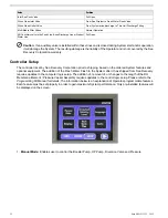
1. From the default screen, touch the
SETUP
tab.
2. On the next screen, touch the
Acceptable Salinity Level
button.
3. On the Salinity Level screen, adjust the salinity to desired level (188 to 370 PPM), then touch the
SETUP
button.
4. On the next screen, touch the
Manual Mode
button.
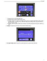
5. On the next screen, touch the Booster Pump
START
button then wait 5 seconds for booster pump to stabilize.
6. Touch the HP Pump
START
button.
7. Slowly increase the high pressure level meter until the System product flow rate if reached.
•
PRODUCT SALINITY (RED)
means that the dissolved solids in the Product Water have not yet decreased
to an acceptable level. Although the system is producing “Product Water,” the Product Water may not be
potable (i.e, drinkable) for up to 30 minutes. The salinity of the Product Water diminishes gradually, until it
reaches an acceptable level or lower.
•
PRODUCT SALINITY (GREEN)
means that the dissolved solids in the Product Water have reached the
acceptable level and the Diversion Valve can be activated.
8. Activate the Diversion Valve. Touch the Diversion Valve button, which will cause the optional UV Sterilizer to
energize, as well as the 3-Way Product Water Diversion Valve to energize. “Potable” (good water) will then be
diverted into Post Filtration and onward to the Ship’s Storage Tank.
Note:
All System readings, pressures, flows and salinity will be displayed on the Main Touch Screen.
Important:
If an abnormality develops, touch the
STOP
button in the top right corner of the screen. A
warning screen will display. Correct the problem and then repeat Steps 1-8.
9. During operation, check for the following conditions:
a) Constant feed water flow.
b) Consistent system pressure.
c) Leaks in the System.
d) Abnormal noises or other occurrences.
49
General Operation
Summary of Contents for Aqua Matic XL Series
Page 2: ......
Page 10: ......
Page 28: ......
Page 38: ......
Page 45: ...45 Commissioning...
Page 46: ......
Page 58: ......
Page 76: ......
Page 89: ...Chapter 10 Appendix 89...
Page 90: ...ABS Certificate of Design Assessment Aqua Matic XL 2200 3600 90...
Page 91: ...FCC Compliance 91 Appendix...
Page 92: ...DNV ISO 9001 Certificate Aqua Matic XL 2200 3600 92...
Page 93: ...Single Phase Electrical Motor Wiring 93 Appendix...
Page 94: ...Three Phase Electrical Motor Wiring Aqua Matic XL 2200 3600 94...
Page 95: ...Three Phase Transformer Wiring 95 Appendix...
Page 96: ...New System Initial Readings Form Aqua Matic XL 2200 3600 96...
Page 97: ...Daily System Readings 97 Appendix...
Page 98: ......
Page 99: ...Chapter 11 Exploded Parts Views 99...
Page 100: ...Exploded Parts View...
Page 103: ...7 8 9 10 11 12 13 14 15 16 17 20 19 18 21 22 23 24 25 26 1 2 3 4 5 6 Exploded Parts View 4...
Page 111: ...14 13 2 16 13 12 3 8 10 9 7 1 5 4 6 14 13 15 15 17 13 12 11 18 15 Exploded Parts View 12...
Page 113: ...19 16 2 21 16 14 3 9 11 10 8 1 5 4 6 12 22 20 18 16 17 15 15 13 7 Exploded Parts View 14...
Page 115: ...2 3 10 12 11 9 1 5 4 21 13 20 18 15 19 18 19 15 17 14 16 8 18 15 7 Exploded Parts View 16...
Page 117: ...10 26 11 9 5 5 4 20 1 7 18 3 2 16 13 15 12 14 13 23 24 21 24 25 Exploded Parts View 18...
Page 119: ...12 10 13 11 5 5 4 6 1 9 20 3 2 17 16 14 18 15 19 17 16 14 18 15 8 7 Exploded Parts View 20...
Page 128: ...6 7 2 3 2 5 10 10 12 1 11 8 9 8 11 6 7 4 2 13 14 29...
Page 138: ...Chapter 12 Electric Diagrams Foldouts 101...
Page 139: ...Aqua Matic XL Series Three Phase Wiring Diagram...
Page 140: ......
Page 141: ......


