Ultraviolet Sterilizer
The UV Sterilizer lamp emits low frequency light. The light degrades and loses intensity, as well as its ability to
sterilize biological matter over approximately 8000 hours of use. Therefore, the lamp may remain lit, but requires
replacement every 4400 to 8000 hours.
Danger:
UV light is harmful to eyes and skin! Check that system power is turned
OFF
before beginning
sterilizer maintenance.
Lamp Replacement
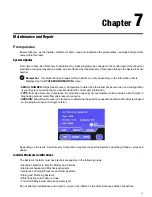
1. Remove the four screws on the ballast box.
2. Remove lid.
3. Remove rubber boot and carefully pull lamp out of quartz sleeve.
4. Replace the lamp.
Note:
During lamp replacement, clean the quartz sleeve as well. The quartz sleeve should be clear. If
discolored, it must be cleaned or replaced.
Quartz Sleeve Cleaning
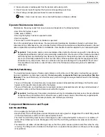
1. Remove the four screws on the ballast box.
2. Remove lid.
3. Remove rubber boot and carefully pull lamp out of the quartz sleeve.
4. Unscrew and remove two compression nuts (ballast box and view port).
5. Remove the O-ring on the view port side only.
6. Carefully pull the quartz sleeve out from the ballast box side.
7. Clean the quartz tube with water and a bottle brush without moving the O-ring. Dry with a soft cloth. Handle the
quartz sleeve carefully.
Reassembly
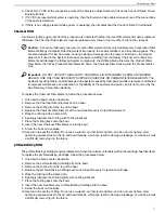
1. Replace old O-rings with new O-rings.
2. Insert the quartz sleeve (close-end first) through the ballast box pass thru until O-ring contact pass thru. Screw
on the ballast box compression nut. Insert view port O-ring and screw on view port compression nut.
3. Attach a new UV Lamp into the plug.
4. Slide the lamp into the Quartz Sleeve and install rubber boot over the compression nut.
5. Replace the three ¼-20 cap head screws.
Fresh Water Flush Carbon Filter Element
The Carbon Filter Element in the Fresh Water Flush must be replaced every three months. The Fresh Water Flush
will automatically flush the system with Fresh Water every preset number of days. The duration of the flush cycle
will be 90 seconds for a system connected to 60 Hz power and to 120 seconds for systems connected to 50 Hz
power. To replace the Carbon Filter Element, follow the procedures below.
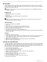
1. Unscrew the bowl counter-clockwise.
2. Remove the Carbon Filter Element from the bowl.
3. Remove the O-Ring from the top of the bowl.
4. Replace the Carbon Filter Element with a new Sea Recovery Corporation element.
5. Wipe the O-Ring with a damp cloth.
6. Sparingly lubricate the O-Ring lightly with O-Ring lubricant.
7. Place the O-Ring back onto the bowl.
8. Insert the new Sea Recovery Carbon Filter Element into the bowl.
9. Screw the bowl on clockwise.
Aqua Matic XL 2200 - 3600
72
Summary of Contents for Aqua Matic XL Series
Page 2: ......
Page 10: ......
Page 28: ......
Page 38: ......
Page 45: ...45 Commissioning...
Page 46: ......
Page 58: ......
Page 76: ......
Page 89: ...Chapter 10 Appendix 89...
Page 90: ...ABS Certificate of Design Assessment Aqua Matic XL 2200 3600 90...
Page 91: ...FCC Compliance 91 Appendix...
Page 92: ...DNV ISO 9001 Certificate Aqua Matic XL 2200 3600 92...
Page 93: ...Single Phase Electrical Motor Wiring 93 Appendix...
Page 94: ...Three Phase Electrical Motor Wiring Aqua Matic XL 2200 3600 94...
Page 95: ...Three Phase Transformer Wiring 95 Appendix...
Page 96: ...New System Initial Readings Form Aqua Matic XL 2200 3600 96...
Page 97: ...Daily System Readings 97 Appendix...
Page 98: ......
Page 99: ...Chapter 11 Exploded Parts Views 99...
Page 100: ...Exploded Parts View...
Page 103: ...7 8 9 10 11 12 13 14 15 16 17 20 19 18 21 22 23 24 25 26 1 2 3 4 5 6 Exploded Parts View 4...
Page 111: ...14 13 2 16 13 12 3 8 10 9 7 1 5 4 6 14 13 15 15 17 13 12 11 18 15 Exploded Parts View 12...
Page 113: ...19 16 2 21 16 14 3 9 11 10 8 1 5 4 6 12 22 20 18 16 17 15 15 13 7 Exploded Parts View 14...
Page 115: ...2 3 10 12 11 9 1 5 4 21 13 20 18 15 19 18 19 15 17 14 16 8 18 15 7 Exploded Parts View 16...
Page 117: ...10 26 11 9 5 5 4 20 1 7 18 3 2 16 13 15 12 14 13 23 24 21 24 25 Exploded Parts View 18...
Page 119: ...12 10 13 11 5 5 4 6 1 9 20 3 2 17 16 14 18 15 19 17 16 14 18 15 8 7 Exploded Parts View 20...
Page 128: ...6 7 2 3 2 5 10 10 12 1 11 8 9 8 11 6 7 4 2 13 14 29...
Page 138: ...Chapter 12 Electric Diagrams Foldouts 101...
Page 139: ...Aqua Matic XL Series Three Phase Wiring Diagram...
Page 140: ......
Page 141: ......


