Commercial Pre-Filter
1.
Problem: The Feed Water Pressure into the Prefilter is higher than normal, and the Feed Water Pressure
into the High Pressure Pump is lower than normal.
a. Description: The pressure differential readings across the Pre-filter indicate that the element is filled with
debris blocking the feed water.
b. Solution: Replace the Pre-filter Element.
Oil and Water Separator
1.
Problem: The Feed Water Pressure into the Oil/Water Separator is higher than normal, and the Feed
Water Pressure into the High Pressure Pump is lower than normal.
a. Description: The pressure differential readings across the Oil/Water Separator indicate that the element is
filled with debris blocking the feed water.
b. Solution: Replace the Oil/Water Separator Element.
Standard HP Pump Assembly
Prior to assuming that the High Pressure Pump’s Electric Motor has failed, perform a function test.
1.
Problems: The Single Phase (115 or 230 VAC) Electric Motor “hums,” pulls starting current (locked
rotor) amperage, does not rotate, and trips the supply power circuit breaker when attempting to operate
the System.
a. Description: The Single Phase Electric Motor is a capacitor start motor. If the motor was started with low
voltage, a drop in voltage during starting, and if this was repeated several times in rapid concession the
capacitor will short out. Without the aid of a working capacitor the motor will “hum”, pull starting current
(locked rotor) amperage, not rotate, and trip the supply power circuit breaker when attempting to operate
the System. Low voltage will also cause the same symptom. Low voltage is caused by an undersized power
supply or generator, undersized power lead wires to the System or motor, loose power wire, or connection
at the motor or within the power supply line, and “burnt” contacts on the motor starter relay (contactor).
b. Solutions:
a. Check wiring size and connections to, from, and in between the Power Supply and the electric motor.
Correct wire size or any loose wires.
b. Check the capacitor on the motor, and replace it if it has shorted out.
c. Measure voltage at the motor during attempt to start it. If voltage drops more than 10% locate and correct
the reason.
d. Check the motor starter relay (contactor) for “burnt” contacts.
2.
Problems: The Three Phase (230/380/460 VAC) Electric Motor “hums,” pulls starting current (locked
rotor) amperage, does not rotate, and trips the supply power circuit breaker when attempting to operate
the System.
a. Description: The Three Phase Electric Motor requires all three power lines (all three phases) to be operative
else it will “single phase” causing extensive damage to the motor’s internal windings. Low voltage will also
cause the same symptom. Low voltage is caused by an undersized power supply or generator, undersized
power lead wires to the System or motor, loose power wire, or connection at the motor or within the power
supply line, and “burnt” contacts on the motor starter relay (contactor).
b. Solutions:
a. Check wiring size and connections to, from, and in between the Power Supply and the electric motor.
Correct wire size or any loose wires.
b. Measure voltage at the motor during attempt to start it. If voltage drops more than 10% locate and correct
the reason.
c. Check the motor starter relay (contactor) for “burnt” contacts.
81
Troubleshooting
Summary of Contents for Aqua Matic XL Series
Page 2: ......
Page 10: ......
Page 28: ......
Page 38: ......
Page 45: ...45 Commissioning...
Page 46: ......
Page 58: ......
Page 76: ......
Page 89: ...Chapter 10 Appendix 89...
Page 90: ...ABS Certificate of Design Assessment Aqua Matic XL 2200 3600 90...
Page 91: ...FCC Compliance 91 Appendix...
Page 92: ...DNV ISO 9001 Certificate Aqua Matic XL 2200 3600 92...
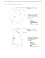
Page 93: ...Single Phase Electrical Motor Wiring 93 Appendix...
Page 94: ...Three Phase Electrical Motor Wiring Aqua Matic XL 2200 3600 94...
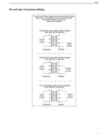
Page 95: ...Three Phase Transformer Wiring 95 Appendix...
Page 96: ...New System Initial Readings Form Aqua Matic XL 2200 3600 96...
Page 97: ...Daily System Readings 97 Appendix...
Page 98: ......
Page 99: ...Chapter 11 Exploded Parts Views 99...
Page 100: ...Exploded Parts View...
Page 103: ...7 8 9 10 11 12 13 14 15 16 17 20 19 18 21 22 23 24 25 26 1 2 3 4 5 6 Exploded Parts View 4...
Page 111: ...14 13 2 16 13 12 3 8 10 9 7 1 5 4 6 14 13 15 15 17 13 12 11 18 15 Exploded Parts View 12...
Page 113: ...19 16 2 21 16 14 3 9 11 10 8 1 5 4 6 12 22 20 18 16 17 15 15 13 7 Exploded Parts View 14...
Page 115: ...2 3 10 12 11 9 1 5 4 21 13 20 18 15 19 18 19 15 17 14 16 8 18 15 7 Exploded Parts View 16...
Page 117: ...10 26 11 9 5 5 4 20 1 7 18 3 2 16 13 15 12 14 13 23 24 21 24 25 Exploded Parts View 18...
Page 119: ...12 10 13 11 5 5 4 6 1 9 20 3 2 17 16 14 18 15 19 17 16 14 18 15 8 7 Exploded Parts View 20...
Page 128: ...6 7 2 3 2 5 10 10 12 1 11 8 9 8 11 6 7 4 2 13 14 29...
Page 138: ...Chapter 12 Electric Diagrams Foldouts 101...
Page 139: ...Aqua Matic XL Series Three Phase Wiring Diagram...
Page 140: ......
Page 141: ......


