background image


Sea Tel, Inc. 

4030 Nelson Avenue 

Concord, CA   94520 
Tel:  (925) 798-7979 

Fax: (925) 798-7986 

Email:  seatel@cobham.com  
Web: : 

www.cobham.com\seatel


Sea Tel Europe 

Unit 1, Orion Industrial Centre 

Wide Lane, Swaythling 
Southampton, UK S0 18 2HJ 

Tel:  44 (0)23 80 671155 

Fax: 44 (0)23 80 671166 

Email:  seatel@cobham.com  

Web: 

www.cobham.com\seatel


Sea Tel Inc doing business as Cobham SATCOM


December 16, 2009   

Document. No. 126843   Revision  D 


CAUTION:


This stabilized antenna system is designed to be used with transmit/receive equipment manufactured 

by others.  Refer to the documentation supplied by the manufacturer which will describe potential hazards, 
including exposure to RF radiation, associated with the improper use of the transmit/receive equipment.  Note that 
the transmit/receive equipment will operate independently of the stabilized antenna system.  

Prior to work on 

the stabilized antenna system, the power to the transmit/receive system must be locked out and 
tagged.


When the transmit/receive system is in operation, no one should be allowed 

anywhere within the radiated 

beam 

being emitted from the reflector. 

The ultimate responsibility for safety rests with the facility operator and the individuals who work 

on the system.


INSTALLATION AND OPERATION 

MANUAL FOR SEA TEL BROADBAND-AT-SEA  

TRANSMIT / RECEIVE SYSTEM 

MODEL: 2406-7  


Summary of Contents for 2406-7

Page 1: ...ation supplied by the manufacturer which will describe potential hazards including exposure to RF radiation associated with the improper use of the transmit receive equipment Note that the transmit receive equipment will operate independently of the stabilized antenna system Prior to work on the stabilized antenna system the power to the transmit receive system must be locked out and tagged When t...

Page 2: ...er 09 1998 The Series 06 Family of Marine Stabilized Antenna Pedestals with DAC 2202 Antenna Control Unit complies with the requirements of European Norms and European Standards EN 60945 1997 and prETS 300 339 1998 03 Sea Tel European Union Declaration of Conformity for this equipment is contained in this manual Copyright Notice All Rights Reserved The information contained in this document is pro...

Page 3: ......

Page 4: ...7 2007 Production Release MDN B N A May 2 2008 Updated text drawings MDN C N A January 23 2009 Change BUC to 8W NJRC Updated text drawings Updated font logo MDN D N A December 16 2009 Updated Text Graphics and Drawings to reflect current build and GSR2 features ECM ...

Page 5: ...ints 3 2 3 1 4 Satellite polarization 3 2 3 2 ANTENNA BASICS 3 2 3 2 1 Unlimited Azimuth 3 2 3 2 2 Elevation 3 3 3 2 3 Antenna Reflector Feed Assembly 3 3 3 2 4 Antenna polarization 3 3 3 2 5 Fixed frequency Dual or Tri band LNBs 3 3 3 2 6 Stabilization 3 3 3 2 7 Search Pattern 3 3 3 2 8 Tracking Receiver Single Channel Per Carrier Receiver 3 3 3 2 9 Tracking 3 4 3 3 COMPONENTS OF THE SYSTEM CONFI...

Page 6: ...TENNA POSITION HOME FLAG OFFSET 5 2 5 5 1 To Calculate HFO 5 2 5 5 2 To Enter the HFO value 5 4 5 6 RADIATION HAZARD AND BLOCKAGE MAPPING AZ LIMIT PARAMETERS 5 4 5 7 TX POLARITY SETUP 5 5 5 8 TRACK DISP 5 5 5 9 DEFAULT SETUP PARAMETERS 5 6 6 FUNCTIONAL TESTING 6 1 6 1 ACU ANTENNA SYSTEM CHECK 6 1 6 2 LATITUDE LONGITUDE AUTO UPDATE CHECK 6 1 6 3 SHIP HEADING GYRO COMPASS FOLLOWING CHECK 6 1 6 4 AZI...

Page 7: ... 7 5 2 Model Configuration Numbers 7 16 8 2406 7 TECHNICAL SPECIFICATIONS 8 1 8 1 ANTENNA REFLECTOR FEED 2406 8 1 8 2 RF EQUIPMENT 8 1 8 3 PEDESTAL CONTROL UNIT 8 1 8 4 STABILIZED ANTENNA PEDESTAL ASSEMBLY 8 2 8 5 RADOME ASSEMBLY 34 8 2 8 6 UNLIMITED AZIMUTH MODEM MULTIPLEXER 3 CHANNEL 8 3 8 7 ADE PEDESTAL POWER REQUIREMENTS 8 3 8 8 ENVIRONMENTAL CONDITIONS ABOVE DECKS EQUIPMENT 8 4 8 9 BELOW DECK...

Page 8: ...2406 7 Broadband At Sea Table of Contents viii This Page Intentionally Left Blank ...

Page 9: ...te modem and then to all of your other below decks computer fax and telephone equipment 1 3 System Components The 2406 TXRX system consists of two major groups of equipment an above decks group and a below decks group Each group is comprised of but is not limited to the items listed below All equipment comprising the Above Decks is incorporated inside the radome assembly and is integrated into a s...

Page 10: ...2406 7 Broadband At Sea Introduction 1 2 THIS PAGE INTENTIONALLY LEFT BLANK ...

Page 11: ...t sensor to level this results in the tilt of the Cross Level Beam being level 4 Azimuth axis activates Antenna drives in azimuth until the Home Flag signal is produced This signal is produced by a Hall Effect sensor coming into close proximity to a Magnet mounted in the azimuth driven sprocket This completes the phases of initialization At this time the antenna elevation should 45 0 degrees and R...

Page 12: ...is routed to the pedestal modem labeled Co Pol The desired output to be sent below decks Co Pol or Cross Pol is selected by connecting the correct coax to the pedestal modem 2 8 RF Equipment The RF Equipment is not operated or controlled by the antenna pedestal or Antenna Control Unit Refer to the vendor supplied manuals for the RF Equipment and Satellite Modem which were provided with your system...

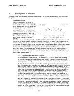
Page 13: ...ather changes in the atmosphere There are several conditions that can cause a temporary loss of satellite signal even within an area where the signal level is known to be adequate The most common of these normal temporary losses are blockage and rain fade They will normally interrupt services only as long as the cause of the loss persists Ku Band Frequency 10 95 12 75GHz Blockage Blockage is loss ...

Page 14: ...olarization The feed assembly installed on your antenna is designed to be fitted with a linear LNB to receive horizontal and vertical linear polarized satellite transmissions A motor which is controlled by the ACU Auto or Manual polarization adjusts the polarization angle of the LNB installed on the feed to optimize the alignment of the LNB to match the angle of the signal from the satellite Auto ...

Page 15: ...r you have installed a different LNB refer to the Maintenance Section of this manual 3 2 5 Your antenna can easily be fitted with a variety of LNBs The LNB must match the frequency band of the desired satellite The Dual Band LNB is able to be electrically switched from low band to high band from the antenna control unit The Tri Band LNB is able to be electrically switched from low band to mid band...

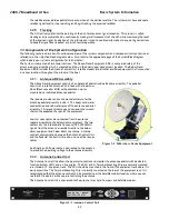
Page 16: ...ish feed with a linear Low Noise Block converter LNB with polarization motor mounted on a stabilized antenna pedestal Antenna ADE Assembly The radome provides an environmental enclosure for the antenna pedestal assembly inside it This keeps wind water condensation and salt water spray off the antenna pedestal assembly This prevents damage and corrosion that would shorten the expected life span of ...

Page 17: ...manual for its power requirements and consumption specifications 3 4 Positive Satellite ID The ACU has the means of positively identifying a satellite either internally DVB compliant transponders or Externally Modem lock indication via Ethernet OpenAMIP or via an analog DC input into the TMS For internal satellite ID all of the DVB receiver parameter settings must be set to match that of the inbou...

Page 18: ... f1 f2 Tracking Frequency 2 Parameters Center Frequency and Bandwidth in MHz H 14123 321 0 256 B f1 f2 Down Conversion Offset 2 parameters LNB Receive Local Oscillator and BUC TX L O B 10750 F Find Target satellite using existing S P R and H Parameters A i Set keep alive in seconds 0 off A 5 L b1 b2 Modem Lock and free to transmit 2 parameters b1 indicates Rx lock and b2 not utilized enables disab...

Page 19: ... s Radar so that it is not directly in the Radar beam path The antenna is a minimum of 15 Feet from high power short wave transmitting antennas The Above Decks Equipment ADE and the Below Decks Equipment BDE should be positioned as close to one another as possible This is necessary to reduce the losses associated with long cable runs The mounting location is rigid enough that it will not flex or s...

Page 20: ...adome base frame are attended while the antenna assembly is being hoisted to its assigned location aboard ship 1 Remove the shipping nuts which mount the ADE to its pallet 2 Using a web strap lifting sling arrangement and with a tag line attached near the radome base hoist the antenna assembly to its assigned location aboard ship by means of a suitably sized crane or derrick 3 The radome assembly ...

Page 21: ... is properly dressed and clamped in place 8 See cable terminations section below 4 5 Cable Installation 4 5 1 Shipboard Cable Installation CAUTION Rough handling tight bending kinking crushing and other careless handling of the cables and their connectors can cause severe damage The cables must be routed from the above decks equipment group through the deck and through various ship spaces to the v...

Page 22: ...te A transmit inhibit output from the ACU will mute the modem transmit when the antenna is mis pointed 0 5 degrees This connection is MANDATORY to comply with new FCC Order 04 286 and WRC 03 Resolution 902 4 6 5 Connect the cable from the ship s gyro compass repeater to TB1 or TB3 of the Terminal mounting strip Use TB1 for a Step By Step gyro compass and match the connections to COM A B and C Use ...

Page 23: ...rify positive satellite identification in a TVRO system verify either Receive NID or that at least one Television is producing video in a VSAT system verify receive lock indication on the satellite modem Access the ACU Setup Mode Parameter AUTO TRIM Press the UP arrow and then press Enter Drive the antenna completely off satellite Target and Azimuth value of 0 Retarget the satellite and verify the...

Page 24: ...ision aligned The Home Switch is a hall sensor which is actuated by a magnet mounted on the azimuth driven sprocket which produces the Home Flag signal The Home Flag Offset is a value saved in NVRam Non Volatile RAM in the PCU This value is the relative position of the antenna when the home switch is engaged Presetting the counter to this value assures that when the antenna is pointed in line with...

Page 25: ...e Calculated position to determine the number of degrees of AZ TRIM that would be required Example In this new installation I target my desired satellite and record the Calculated Azimuth to be 180 5 I drive UP and finally find my desired satellite at a Peak Azimuth of 227 0 degrees I subtract Peak from Calculated and difference to be 46 5 degrees therefore the actual Relative position that needs ...

Page 26: ...HT arrow key to enter writing mode and then press the ENTER to save the HFO value in the PCUs NVRAM EXAMPLE In the Antenna stopped before the Bow example above the HFO calculated was 222 To enter this value 1 Set the Remote Command value to N6222 2 Press ENTER to send this HFO to the PCU The display should now show N0222 3 When completed you must save the desired HFO value Press ENTER several time...

Page 27: ...eter set the selections that the user will see in the Tracking Band Selection menu Band Selection must be set to the appropriate selection for Tracking to operate properly Band selection controls the local logic output state of SW1 output terminal on the Terminal Mounting Strip PCB and remote C Ku relays or other switches on the antenna pedestal The factory default selections and SW1 status for yo...

Page 28: ... in depth information each of the individual parameters and how to enter or change the parameters PARAMETER DishScan My Parameters EL TRIM 0 AZ TRIM 0 AUTO THRES 60 EL STEP SIZE 0 AZ STEP SIZE 0 STEP INTEGRAL 0 SEARCH INC 10 SEARCH LIMIT 100 SEARCH DELAY 30 SWEEP INC 0000 SYSTEM TYPE 5 GYRO TYPE 2 NMEA SBS POL TYPE 72 POL OFFSET 40 POL SCALE 90 AZ LIMIT 1 0 AZ LIMIT 2 0 EL LIMIT 12 0900 AZ LIMIT 3...

Page 29: ...ess the NEXT key repeatedly to display the Ship menu If the boat is underway monitor the Heading value to verify that the display changes in the correct response to the Gyro Compass input Heading value should always be exactly the same as the Gyro Compass repeater value 2 If the ship is NOT underway most ships will turn 1 2 degrees at the pier monitor the Heading value to verify that the display c...

Page 30: ...transmissions while the antenna is pointed where people would be harmed by the transmitted microwave RF power output The SW2 output would be interfaced to the satellite modem to disable the TX output signal from the Satellite TXRX Modem whenever the antenna is within the RF Radiation Hazard zone s When used for FCC TX Mute logic output for a single Sea Tel TX RX antenna this output could be used t...

Page 31: ...am being emitted from the reflector The ultimate responsibility for safety rests with the facility operator and the individuals who work on the system 7 1 Warranty Information Sea Tel Inc supports its Series 97 00 06 and 07 systems with a ONE YEAR warranty on parts and labor What s Covered by the Limited Warranty The Sea Tel Limited Warranty is applicable for parts and labor coverage to the comple...

Page 32: ...n the base pan of the radome to allow standing water to weep out 2 Antenna Pedestal Inspection The shock vibration springs and or wire rope Isolators should not be frayed completely compressed or otherwise damaged The plated and painted parts should not be rusted or corroded The harnesses should not be frayed and all the connectors should be properly fastened and tightened All hardware should be t...

Page 33: ...two axis tilt sensor in the level cage assembly The Azimuth reference is provided by combining the ships gyro compass input and the antenna relative position 7 3 2 Turn the pedestal power supply ON The PCU will initialize the stabilized portion of the mass to be level with the horizon and at a prescribed Azimuth and Elevation angles The antenna will go through the specific sequence of steps listed...

Page 34: ... system maintain the satellite link after turning off TRACKING Tracking is the process of issuing fine adjustments to the pointing angle of the antenna to optimize the received signal level and is controlled by the ACU Does the system pass a four quadrant tracking test Functional Test s DacRemP Graph Selection to use System Function s Four Quadrant Tracking ADMC Position Tracking Azimuth Encoder V...

Page 35: ...desired position the PCU will flag a Stab Limit error Antenna Loop Error Monitoring To view the position error select the graph chart This chart displays sensed axis errors via three traces CL Cross Level LV Elevation and AZ Azimuth at a fixed 0 05º vertical division The normal trace average will plots it s display 3 divisions from the red reference line Any trace line average plotted above this i...

Page 36: ...rs select the graph chart This chart displays the output of the Tilt Sensor via two traces CL Cross Level LV Elevation at a fixed 1º vertical division and the home flag logic level via a single trace AZ Azimuth The normal trace display for the Tilt Sensor after performing remote tilt calibration will be 4 divisions from the red reference line Any trace line average plotted above this is of concern...

Page 37: ...ee below for a screen capture of an antenna that was driven so that the Home Flag switch is engaged 7 3 6 The DacRemP DISPW graph chart provides a means for monitoring the output of the 3 solid state rate sensors located inside the Level Cage Assembly for diagnostic purposes The rate sensors are the primary inputs to the PCU for stabilization Open Loop Rate Sensor Monitoring To monitor the rate se...

Page 38: ...s tilted back The Azimuth display should decrease plots below red line as the antenna is rotated CCW and increase plots above red line as the antenna is rotated CW In the example below the output of the Azimuth rate sensor is plotted above the reference line indicating that the antenna was driven CW in Azimuth Due to the in practicality of driving an axis at a consistent rate verification of rate ...

Page 39: ... set to 0000 you will get a constant ERROR 0016 DishScan error and you will see zeros flashing in the lower left of the Azimuth and Elevation ENTRY menu displays This is a visual indication that DishScan is turned OFF 7 3 9 The ships gyro compass input to the ACU may be accurate and stable in static conditions and yet may NOT be accurate or stable enough in some underway dynamic conditions If ther...

Page 40: ...NTER key to turn Satellite Reference Mode OFF If you change this remote parameter you must save the change using REMOTE PARAMETERS 7 3 10 An Error Code 8 as reported by the ACU is an indication that the above decks equipment has experienced an error One of the functions available within the Comm Diagnostics tool window provides the means to read and decode the actual discreet Pedestal Function Err...

Page 41: ...or unlimited azimuth antenna systems Data 3 Indicates active communication between above decks and below decks equipment at the time of query Data 2 Indicates active communication between above decks and below decks equipment at the time of query PCU Status Word 2 Az Target Indicates the antenna is currently targeting a pre determined azimuth position Az Velocity Not a valid state Valid Heading PC...

Page 42: ... Servo Amplifier motor driver PCB has exceeded what is required during normal operation CL Servo Limit Indicates the current draw through the Cross Level Servo Amplifier motor driver PCB has exceeded what is required during normal operation 7 3 11 The above decks equipment has an integrated on board Furuno GPS antenna system The Latitude and Longitude position information provided are utilized to ...

Page 43: ...itude position The status character tells you the status of the GPS Comma GPS has NOT acquired a proper fix N GPS fix is NOT valid A GPS has acquired a valid fix 7 4 Maintenance 7 4 1 The antenna and equipment frame are balanced at the factory however after disassembly for shipping or maintenance balance adjustment may be necessary Balancing must be done with the power supply turned OFF No belt re...

Page 44: ...the two LEFT RIGHT arrows until the EL TRIM parameter is displayed 2 Press and release both Left Right arrow keys again The SAVE NEW PARAMETERS window should now be displayed 3 Press either the ENTER key or the DOWN key until the REMOTE DishScan TG parameter is displayed 4 Press the RIGHT arrow to activate selection then press the Up arrow to toggle state to OFF Press the ENTER key Note You will s...

Page 45: ...REMOTE PARAMETERS window is displayed 2 Press RIGHT arrow and then press ENTER key you will see a confirmation saying SAVED Using DacRemP 5 Click icon on the Remote Command window Verify 0087 is displayed in the Last Sent Command window This saves the new tilt bias settings in the PCU Reset or re initialize the antenna to verify that the Level cage is properly level with the new settings 7 4 3 To ...

Page 46: ...he three torque motors to prevent damage to the unknown pedestal 7 5 1 To configure the PCU 1 Select the REMOTE COMMAND window on the ACU 2 Refer to the table below to key in the appropriate value for you model antenna to enter in the next step EXAMPLE For a 4006 Model Antenna select system type 0020 3 Using the LEFT RIGHT and UP DOWN arrow keys set the Remote Command value to N0020 and press ENTE...

Page 47: ... Gain 34 dBi at 10 75 GHz Typical in the Radome Transmit frequency range 14 0 14 5 GHz Ku Band Receive frequency range 10 95 12 75 GHz Ku Band 8 2 RF Equipment 8W SSPBUC Block Up Converter NJRC 5118N Ku Band 8 Watt Transmit Frequency 14 0 14 5 GHz Input IF Frequency 950 1450 MHz External Reference 10 MHz sine wave Local Oscillator Frequency 13 05 GHz Linear Gain 59 dB min DC Power Requirement 18 t...

Page 48: ...to 75 degrees at maximum combined roll pitch Maximum Specified Ship Motions Roll 25 degrees Pitch 15 degrees Yaw Unlimited Specified Ship Motions for stabilization accuracy tests Roll 20 degrees at 8 12 sec periods Pitch 10 degrees at 6 12 sec periods Yaw 8 degrees at 15 to 20 sec periods Turning rate Up to 12 deg sec and 15 deg sec sec Headway Up to 50 knots Mounting height Up to 150 feet Heave 0...

Page 49: ...9 pin D Sub Connector Pedestal M C Modulation FSK Mode Full Duplex Frequencies 1 1 1 5 MHz Combined Signals 5 Pass Thru 70 140 950 2050 MHz RX IF 22Khz Tone Injected 1 1 1 5Mhz Pedestal M C DC LNB Voltage Select Connectors RX IF F female Rotary Joint SMA female DC Ped M C 9 pin D Sub Connector Pedestal M C Modulation FSK Mode Full Duplex Frequencies 1 1 1 5 MHz 8 7 ADE Pedestal Power Requirements ...

Page 50: ...mposed vibrations in all 3 axes having displacement amplitudes as follows Frequency Range Hz Peak Single Amplitude 4 10 0 100 inches 0 16 to 1 0G 10 15 0 030 inches 0 3 to 0 7G 15 25 0 016 inches 0 4 to 1 0G 25 33 0 009 inches 0 6 to 1 0G Corrosion Parts are corrosion resistant or are treated to endure effects of salt air and salt spray The equipment is specifically designed and manufactured for m...

Page 51: ...lent conductor size for our standard pedestal installations Run Length Coax Type Center Conductor Size Typ Loss 1750Mhz up to 150 ft LMR 400 14 AWG 5 571 db 100 up to 200 ft LMR 500 10 AWG 4 496 db 100 Up to 300 ft LMR 600 6 AWG 3 615 db 100 8 10 3 AC Power Cable Above Decks Customer Furnished Voltage 110 or 220 volts AC 50 60 Hz single phase Type Multi conductor Shielded Number of wires 3 Conduct...

Page 52: ...2406 7 Broadband At Sea 2406 7 Technical Specifications 8 6 This Page Intentionally Left Blank ...

Page 53: ...agram 9 5 129071 1_B 2406 7 General Assembly 9 8 129074_A1 Antenna System Schematic 9 10 129299 3_B 2406 Antenna Assembly 9 11 125808 1_A3 34 Radome Assembly 9 13 122663_B5 Installation Arrangement 9 16 9 2 2406 General Drawings Drawing Title 127421 1 Standard Spare Parts Kit 9 17 127422 1 Premium Spare Parts Kit 9 18 127423 1 Master Spare Parts Kit 9 19 124348_B4 Pedestal Harness Schematic 9 20 1...

Page 54: ...2406 7 Broadband At Sea DRAWINGS 9 2 This Page Intentionally Left Blank ...

Page 55: ...2 SCPC RCVR 9 WIRE IF 8 1 EA 123752 4 C BELOW DECK KIT L BAND PED M C 9 1 EA 128541 1 A SSPB KU BAND 8W NJT5118N N TYPE 16 1 EA 121711 A BALANCE WEIGHT KIT 17 1 EA 127004 CUSTOMER DOC PACKET 2406 21 2 EA 114239 A SIGN WARNING MICROWAVE 42 1 EA 123324 2 A SHIP STOWAGE KIT XX04 XX03 24XX 1 SHT 1 OF SYSTEM 2406 7 LIN 8W NO LNB 34 INCH DOME PROD FAMILY SERIES 06 EFF DATE 12 16 2009 DRAWING NUMBER 1290...

Page 56: ......

Page 57: ...M EXIT 080 P 25 1 EA 116708 H HALL EFFECT ENCLOSURE ASS Y 26 1 EA 121966 D2 GPS ANTENNA RETERMINATED 90 0 L 30 1 EA 129359 2 X4 HARNESS ASS Y INTERFACE NJRC 8W 31 1 EA 122223 4 F1 HARNESS ASS Y PEDESTAL REFERENCE 32 1 EA 124213 3 D HARNESS ASS Y 3BLDC 2406 33 1 EA 121485 1 G HARNESS ASS Y REFLECTOR 40 1 EA 127940 1 A POWER RING ASS Y 22 IN 66 IN CONTA 41 1 EA 124288 24 G CABLE ASS Y AC POWER 24 IN...

Page 58: ...05 1 EA 117168 2 P1 MODEM ASS Y BASE 3 CH 75 OHM 110 1 EA 113303 10 T1 CABLE ASS Y SMA 90 SMA M 8 IN 112 2 EA 111115 6 B CABLE ASS Y F M F M 6 FT 113 1 EA 116700 6 F CABLE ASS Y RG223 N M F M 6 FT 114 1 EA 114973 72 E CABLE ASS Y N M N M 72 IN 115 1 EA 116298 1 G INTERFACE HARNESS ASS Y DUAL MODEM 116 1 EA 120643 25 B CABLE ASS Y RS232 9 WIRE STRAIGHT 117 1 EA 119479 10 B CABLE ASS Y CAT5 JUMPER 1...

Page 59: ......

Page 60: ... SMA 14 1 12 1 EA 119318 5 D WAVEGUIDE WR 75 90 DEG H BEND 3 00 13 1 EA 118294 1 A3 HARDWARE KIT WR 75 UG FLANGE 6 32 14 1 EA 118294 6 A3 HARDWARE KIT WR 75 UG FLANGE M4 21 1 EA 126797 12 A CABLE ASS Y ST 18 SMA M SMA M 22 1 EA 115492 16 C3 ADAPTER SMA M SMA F 45 DEGREE DC 42 2 EA 114586 553 SCREW HEX HD 1 4 20 x 5 S S 60 2 EA 114583 029 NUT HEX 1 4 20 S S 62 4 EA 114580 027 WASHER FLAT 1 4 SMALL ...

Page 61: ......

Page 62: ......

Page 63: ... WASHER LOCK 4 S S 52 4 EA 114580 006 WASHER FLAT 4 SMALL PATTERN S S 60 4 EA 119961 007 NUT HEX SMALL PATTERN 6 32 S S 61 4 EA 114581 007 WASHER LOCK 6 S S 62 4 EA 114580 008 WASHER FLAT 6 SMALL PATTERN S S 70 4 EA 114588 829 SCREW PAN HD PHIL 10 32 x 1 2 S S 71 12 EA 114580 011 WASHER FLAT 10 S S 72 6 EA 114583 011 A NUT HEX 10 32 S S 73 2 EA 114588 831 SCREW PAN HD PHIL 10 32 x 3 4 S S 2 SHT 1 ...

Page 64: ... C B A A B C D 1 2 3 4 5 6 7 8 8 7 6 5 4 3 2 DESCRIPTION DATE 4030 NELSON AVENUE Tel 925 798 7979 Fax 925 798 7986 Tel UNLESS OTHERWISE SPECIFIED CONCORD CA 94520 PROJECTION FINISH Sea 3rd ANGLE DIMENSIONS ARE IN INCHES DRAWN BY APPROVED BY TITLE FIRST USED SIZE SCALE SHEET NUMBER DRAWING NUMBER REV K D H BY B N A N A 2406 51 1 2 OPTIM 24 IN TX RX A 1 OF 1 MATERIAL 1 DRAWN DATE ECO REV 129299 REVI...

Page 65: ...25 0 CABLE CLAMP NYLON 3 4 DIA 10 MTG 10 1 OZ 125948 1 A ADHESIVE HOT MELT 3M SCOTCH WELD 37 NOT SHOWN 11 2 EA 110481 4 G DECAL LOGO SEA TEL 16 X 6 3 IN 16 1 EA 123549 F KIT RADOME HARDWARE MOUNTING 50 2 EA 114588 190 SCREW PAN HD PHIL 8 32 x 1 4 S S 53 4 EA 114588 191 SCREW PAN HD PHIL 8 32 x 5 16 S S 54 6 EA 114580 009 WASHER FLAT 8 S S 60 3 EA 114588 198 SCREW PAN HD PHIL 8 32 x 7 8 S S 61 3 EA...

Page 66: ......

Page 67: ......

Page 68: ......

Page 69: ......

Page 70: ... KIT 2406 STANDARD 2 1 EA 117168 2 P1 MODEM ASS Y BASE 3 CH 75 OHM 3 1 EA 117168 1 P1 MODEM ASS Y PEDESTAL 3 CH 75 OHM 4 1 EA 125570 2 H POWER SUPPLY ASS Y COSEL 150W RH EN 5 1 EA 114789 810 TRANSPORT CONTAINER 1 SHT 1 OF SPARE PARTS KIT 2406 PREMIUM PROD FAMILY COMMON EFF DATE 12 16 2009 DRAWING NUMBER 127422 1 REV A ...

Page 71: ...127422 1 A SPARE PARTS KIT 2406 PREMIUM 2 1 EA 121250 1 C3 POWER RING ASS Y 22 IN 66 IN CONTA 3 1 EA 116466 D ROTARY JOINT 4 5 GHz DUAL COAX 4 1 EA 121966 D2 GPS ANTENNA RETERMINATED 90 0 L 1 SHT 1 OF SPARE PARTS KIT 2406 MASTER PROD FAMILY COMMON EFF DATE 12 16 2009 DRAWING NUMBER 127423 1 REV B ...

Page 72: ......

Page 73: ... B1 CABLE ASS Y D SUB 9 PIN 36 IN 7 2 EA 121228 3072 STANDOFF HEX F F 6 32 X 25 OD X 9 2 EA 114588 146 SCREW PAN HD PHIL 6 32 x 3 8 S S 11 8 EA 114588 107 SCREW PAN HD PHIL 4 40 x 5 16 S S 19 2 EA 114588 144 SCREW PAN HD PHIL 6 32 x 1 4 S S 29 1 EA 119478 5 C3 CABLE ASS Y RJ 45 SERIAL 60 IN 30 1 EA 126877 B1 HARNESS ASS Y COMTECH MODEM INTERFAC 1 SHT 1 OF TERMINAL MOUNTING STRIP ASS Y ACU PROD FAM...

Page 74: ......

Page 75: ...PAN HD PHIL 4 40 x 5 16 S S 6 8 EA 114583 005 NUT HEX 4 40 S S 7 2 EA 114588 144 SCREW PAN HD PHIL 6 32 x 1 4 S S 8 6 EA 114580 007 WASHER FLAT 6 S S 9 1 EA 110567 19 ADAPTER N F N F STRAIGHT FLANGE 10 1 EA 110567 11 ADAPTER N M F F STRAIGHT 11 1 EA 113303 10 T1 CABLE ASS Y SMA 90 SMA M 8 IN 12 8 EA 114580 005 WASHER FLAT 4 S S 13 4 EA 114588 145 SCREW PAN HD PHIL 6 32 x 5 16 S S 1 SHT 1 OF BASE M...

Page 76: ......

Reviews: