Set-up & Configuration
2406-7 Broadband At Sea
5-3
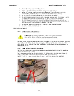
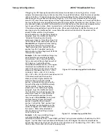
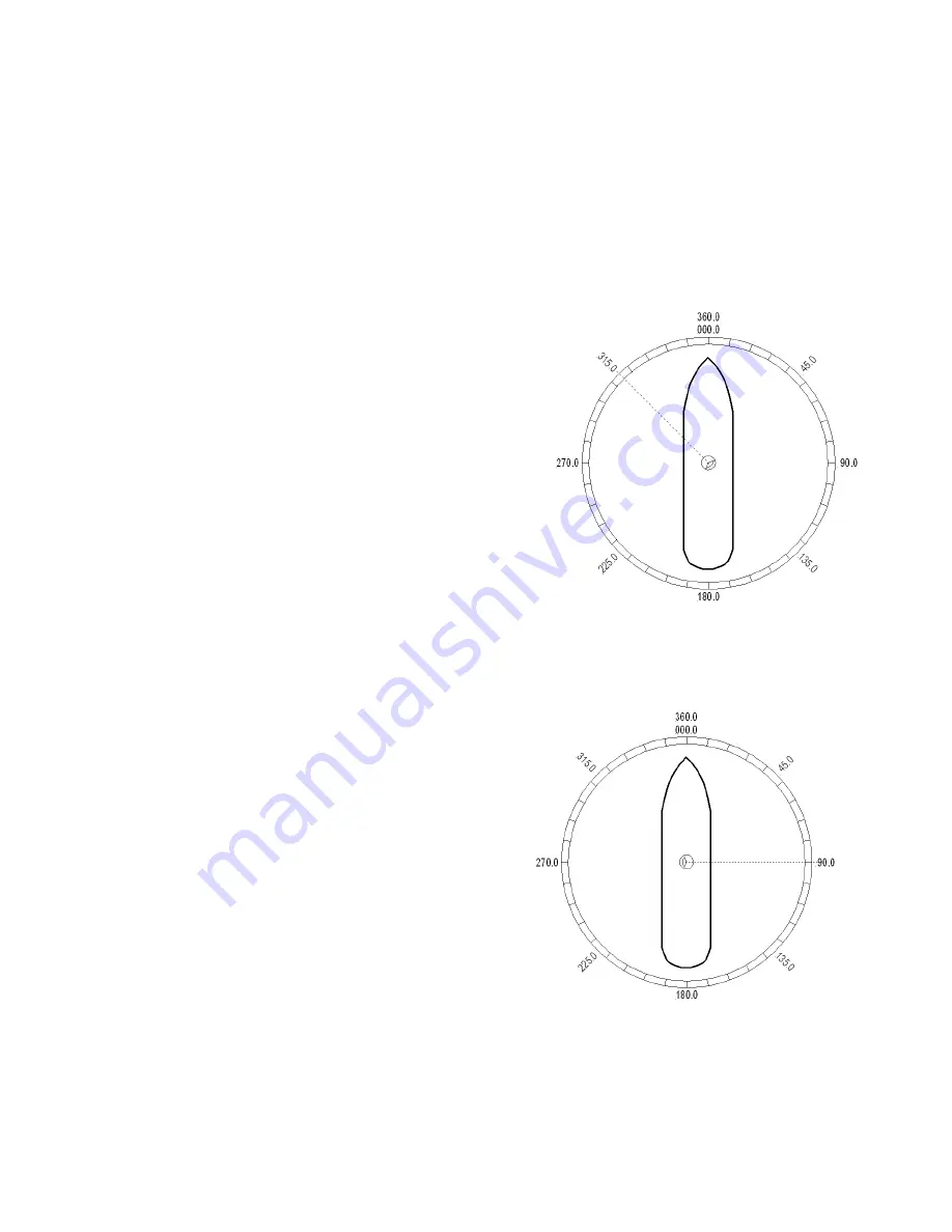
Figure 5-2 Antenna stopped before the Bow
Figure 5-3 Antenna stops past the Bow
If Targeting has NOT been optimized, allow the antenna to initialize to its home flag position. Visually
compare the antennas pointing to the bow-line of the ship (parallel to the Bow). Note the antennas position
relative to the Bow. If it appears to be very close to being parallel to the bow, HFO will probably not be
needed and you can proceed with Optimizing Targeting. If it is NOT close [initialization was driving the
azimuth CW], note if the antenna appears to have stopped before it got to the Bow or if it went past the Bow.
You may be able to guess an approximate amount of how many degrees the antenna is from the bow. This is
only intended to help you initially find the satellite (which direction you will have to drive and approximately
how far you will have to drive). Refer, in general terms, to the Optimizing Targeting procedure.
If the antenna stopped before it got to the bow-line; When you initially target a satellite, the antenna will
also stop prior to the satellite position, so you that will have to drive the Azimuth of the antenna UP to
actually find the satellite. Using the same
basic procedure as in the Optimizing Targeting
paragraph, target the satellite and record the
“Calculated” Azimuth position that the
antenna was driven to. Drive UP until you find
the satellite, positively identify that you are on
the
satellite
you targeted and allow tracking
to peak the antenna position. Record the
“Peak” Azimuth position. Subtract the “Peak”
position from the “Calculated” position to
determine the number of degrees of AZ TRIM
that would be required.
Example:
In this new installation, I target my
desired satellite and record the Calculated
Azimuth to be 180.5. I drive UP and finally
find my desired satellite at a Peak Azimuth of
227.0 degrees. I subtract Peak from
Calculated and difference to be –46.5 degrees,
therefore the actual Relative position that
needs to be preset into the counter when the
antenna is at the Home Flag is 313.5. HFO =
((360-46.5) / 360)) x 255 = (313.5 / 360) x
255 = 0.87 x 255 = 222.06 which I round down to 222.
If the antenna went past the bow-line;
When you initially target a satellite, the
antenna will also go past the satellite
position, so that you will have to drive the
Azimuth of the antenna DOWN to actually
find the satellite. Using the same basic
procedure as in the Optimizing Targeting
paragraph, target the satellite and record
the “Calculated” Azimuth position that the
antenna was driven to. Drive DOWN until
you find the satellite, positively identify
that you are on
the satellite
you targeted
and allow tracking to peak the antenna
position. Record the “Peak” Azimuth
position. Subtract the “Peak” position from
the “Calculated” position to determine the
number of degrees of AZ TRIM that would
be required. . Refer to the calculations
above to determine the HFO you should
use for this antenna.
Example:
In this new installation, I target
my desired satellite and record the
Calculated Azimuth to be 180.0. I drive DOWN and finally find my desired satellite at a Peak Azimuth of 90.0
degrees. I subtract Peak from Calculated and difference to be +90.0 degrees, therefore the actual Relative
position that needs to be preset into the counter when the antenna is at the Home Flag is 90.0. HFO = ((90.0)
/ 360)) x 255 = 0.25 x 255 = 63.75 which I round up to 64.
Summary of Contents for 2406-7
Page 3: ......
Page 8: ...2406 7 Broadband At Sea Table of Contents viii This Page Intentionally Left Blank ...
Page 10: ...2406 7 Broadband At Sea Introduction 1 2 THIS PAGE INTENTIONALLY LEFT BLANK ...
Page 54: ...2406 7 Broadband At Sea DRAWINGS 9 2 This Page Intentionally Left Blank ...
Page 56: ......
Page 59: ......
Page 61: ......
Page 62: ......
Page 66: ......
Page 67: ......
Page 68: ......
Page 69: ......
Page 72: ......
Page 74: ......
Page 76: ......

