background image

Sea Tel, Inc. 
4030 Nelson Avenue 
Concord, CA   94520 
Tel:  (925) 798-7979 
Fax: (925) 798-7986 
Email:  seatel@seatel.com  
Web:    www.seatel.com


Look to the Leader. Look to Sea Tel.


Sea Tel Europe 
Unit 1, Orion Industrial Centre 
Wide Lane, Swaythling 
Southampton, UK S0 18 2HJ 
Tel:  44 (0)23 80 671155 
Fax: 44 (0)23 80 671166 
Email:  europe@seatel.com 
Web:    www.seatel.com


July 9, 2007 


Document. No. 125135 


Rev 


CAUTION:


This stabilized antenna system is designed to be used with transmit/receive equipment 

manufactured by others.  Refer to the documentation supplied by the manufacturer which will 
describe potential hazards, including exposure to RF radiation, associated with the improper use of 
the transmit/receive equipment.  Note that the transmit/receive equipment will operate independently
of the stabilized antenna system.  

Prior to work on the stabilized antenna system, the power to 

the transmit/receive system must be locked out and tagged.


When the transmit/receive system is in operation, no one should be allowed 

anywhere within the 

radiated beam 

being emitted from the reflector. 

The ultimate responsibility for safety rests with the facility operator and the individuals who 
work on the system.


INSTALLATION AND OPERATION 

MANUAL FOR SEA TEL BROADBAND-AT-SEA  

TRANSMIT / RECEIVE SYSTEM 

MODEL: 4006-23  IN A 60” RADOME 


Summary of Contents for 4006-23 IN A 60" RADOME

Page 1: ...ufacturer which will describe potential hazards including exposure to RF radiation associated with the improper use of the transmit receive equipment Note that the transmit receive equipment will operate independently of the stabilized antenna system Prior to work on the stabilized antenna system the power to the transmit receive system must be locked out and tagged When the transmit receive syste...

Page 2: ...nna Control Unit complies with the requirements of European Norms and European Standards EN 60945 1997 and prETS 300 339 1998 03 Sea Tel European Union Declaration of Conformity for this equipment is contained in this manual Copyright Notice All Rights Reserved The information contained in this document is proprietary to Sea Tel Inc This document may not be reproduced or distributed in any form wi...

Page 3: ......

Page 4: ...te Description By A N A February 9 2006 Initial Production Release includes FCC TX Mute function information MDN B N A July 17 2006 Updated text and drawings MDN C 5499 July 9 2007 Change ACU to DAC 2202 Update text and drawings MDN ...

Page 5: ... 3 1 3 1 SATELLITE BASICS 3 1 3 1 1 Ku Band Frequency 10 95 12 75GHz 3 1 3 1 2 Signal level 3 2 3 1 3 Satellite Footprints 3 2 3 1 4 Satellite polarization 3 2 3 2 ANTENNA BASICS 3 3 3 2 1 Unlimited Azimuth 3 3 3 2 2 Elevation 3 3 3 2 3 Antenna Reflector Feed Assembly 3 3 3 2 4 Antenna polarization 3 3 3 2 5 Interchangeable LNBs 3 4 3 2 6 Stabilization 3 4 3 2 7 Search Pattern 3 4 3 2 8 Tracking R...

Page 6: ...IZING TARGETING 5 1 5 3 OPTIMIZING AUTO POLARIZATION TX RX 5 1 5 4 CALIBRATING RELATIVE ANTENNA POSITION HOME FLAG OFFSET 5 2 5 4 1 To Calculate HFO 5 3 5 4 2 To Enter the HFO value 5 4 5 5 RADIATION HAZARD AND BLOCKAGE MAPPING AZ LIMIT PARAMETERS 5 5 5 6 TX POLARITY SETUP 5 8 5 7 DEFAULT SETUP PARAMETERS 5 9 5 8 CONFIGURING YOUR LAN COMPUTER S 5 10 5 8 1 To configure Setup Computer with MS Window...

Page 7: ...e Reference Mode 7 6 7 3 9 To Read Decode an ACU Error Code 0008 Pedestal Error 7 7 7 3 10 Get Remote GPS LAT LON Position 7 8 7 4 MAINTENANCE 7 8 7 4 1 Balancing the Antenna 7 8 7 4 2 24 VDC Polang Alignment 7 9 7 4 3 To Adjust Tilt 7 9 7 4 4 To Reset Reinitialize the Antenna 7 10 7 5 PEDESTAL CONTROL UNIT CONFIGURATION SERIES 06 7 10 7 5 1 To configure the PCU 7 10 7 5 2 Model Configuration Numb...

Page 8: ...ded from ACU MUX 8 4 8 10 2 Antenna L Band IF Coax Cables Customer Furnished 8 4 8 10 3 Multi conductor Cables Customer Furnished 8 5 8 10 4 AC Power Cable Above Decks Customer Furnished 8 5 8 10 5 Gyro Compass Interface Cable Customer Furnished 8 5 9 DRAWINGS 9 1 9 1 4006 23 KU BAND MODEL SPECIFIC DRAWINGS 9 1 9 2 4006 GENERAL DRAWINGS 9 1 ...

Page 9: ...lephone fax and high speed data applications Your antenna system can transmit to and receive from any desired Ku band satellite which has adequate signal coverage in your current geographic area This input will be distributed to your satellite modem and then to all of your other below decks computer fax and telephone equipment 1 3 System Components The 4006 TXRX system consists of two major groups...

Page 10: ...Above Decks Equipment its operation and installation Refer to the manual provided with your Antenna Control Unit for its installation and operating instructions 1 5 Quick Overview of contents The information in this manual is organized into chapters Operation basic system information installation setup functional testing maintenance specifications and drawings relating to this Antenna are all cont...

Page 11: ...level this results in the dish being at an elevation angle of 45 0 degrees 3 Cross Level axis activates Input from the CL axis of the tilt sensor is used to drive Cross Level of the equipment frame to bring the cross level axis of the tilt sensor to level this results in the tilt of the Cross Level Beam being level 4 Azimuth axis activates Antenna drives in azimuth until the Home Flag signal is pr...

Page 12: ...er the matrix switch and satellite receiver s have AC power connected to them Satellite signals are linear polarized fixed plane down from the satellite and therefore the pedestal will only receive linear polarized signals when a linear LNB is installed 2 8 RF Equipment The RF Equipment is not operated or controlled by the antenna pedestal or Antenna Control Unit Refer to the vendor supplied manua...

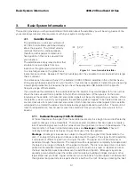
Page 13: ... will appear to be rotated clockwise or counter clockwise from pure horizontal and vertical Both horizontal and vertical signals from a satellite will appear to be rotated the same amount and are always perpendicular to each other The amount of rotation is dependent on how far east or west the satellite is from you and how close you are to the Equator 3 1 1 Ku Band Frequency 10 95 12 75GHz At thes...

Page 14: ...e the desired satellite services until entering or re entering an area of adequate signal level refer to the satellite footprint information Systems with larger diameter dish antennas can receive signal further out towards the fringe of a given satellites coverage area 3 1 3 Satellite Footprints The focused beam s from the satellites are normally aimed at the major land masses where there are larg...

Page 15: ...evation between 00 0 horizon and 90 0 zenith Elevation drive provided by the elevation motor is required during stabilization searching and tracking operations of the antenna The actual elevation pointing angle to the satellite is determined by your latitude longitude and the longitude of the satellite In general terms the elevation angle will be low when the ship is at a high latitude and will in...

Page 16: ...he Satellite Identification Receiver located in the Antenna Control Unit ACU is used to acquire identify and track a specific satellite by a unique network ID code NID Some TVRO signals may not allow the NID to be demodulated In these cases the ACU may be programmed to generate its own ID based on a pattern match comprised of frequency baud rate and FEC rate In addition an external modem lock inpu...

Page 17: ...between the Antenna Control Unit and the Pedestal Control Unit are also on one of these coax cables And finally an AC Power cable is also routed to the antenna to provide the operating voltage to the antenna assembly 3 3 2 Antenna Control Unit The Antenna Control Unit allows the operator to control and monitor the antenna pedestal with dedicated function buttons LED s and a 2 line display The ACU ...

Page 18: ...nd surge protected Uninterrupted Power Supplies are frequently installed below decks to provide power for the antenna pedestal especially if RF Equipment is installed on the pedestal Refer to the Specifications section of this manual for the power consumption of the antenna pedestal and RF Equipment Marine Air Conditioner Unit TX RX Systems ONLY If a marine air conditioner is included with your sy...

Page 19: ...p s Radar so that it is not directly in the Radar beam path 4 The antenna is a minimum of 15 Feet from high power short wave transmitting antennas 5 The Above Decks Equipment ADE and the Below Decks Equipment BDE should be positioned as close to one another as possible This is necessary to reduce the losses associated with long cable runs 6 The mounting location is rigid enough that it will not fl...

Page 20: ...ssible to the centerline of the ship Any variation from actual alignment can be compensated with the AZIMUTH TRIM adjustment in the Antenna Control Unit so precise alignment is not required 4 Bolt the radome base directly to the ship s deck or mounting plate When completed the radome base should be as near level as possible 4 4 2 Antenna Pedestal Mechanical Checks 1 Open the radome hatch and enter...

Page 21: ...In The Radome The TX RX and AC Power cables must be inserted through the cable strain relief s through the base of the radome and connected appropriately The IF Coaxes are connected coax connector bracket The AC Power cable should be routed through the clamp in the end of the breaker box and terminated to the breaker screw terminals Apply RTV to the strain relief joints and tighten the compression...

Page 22: ...er strip 7 Plug the power cord into a suitable 110 or 220 VAC UPS or AC power outlet 4 6 3 Antenna Control Unit Connections The DAC 2200 ACU is installed in a BDE Rack and is one rack unit high It includes a Terminal Mounting Strip mounted on the rear of the rack which is also a one rack unit high plate 4 6 4 Terminal Mounting Strip Connections You will connect you Ships Gyro Compass input to the ...

Page 23: ...tors on the TX and RX IF cables from above decks equipment to the BDE Rack Attach the TX cable to the Satellite Modem TX connection Attach the RX cable to the Base Multiplexer panel RX connector on the rear of the BDE Rack RX IF cable from one output of the splitter mounted on the Base Multiplexer panel is connected to the Satellite Modem RX connection 4 6 9 AGC Tracking Input Connections The othe...

Page 24: ...4006 23 Broadband At Sea Installation 4 6 This Page Intentionally Left Blank ...

Page 25: ...ng ON allow the antenna to Search for the targeted satellite and assure that it has acquired and peaks up on the satellite that you targeted Allow several minutes for the antenna to peak on the signal and then record the Azimuth and Elevation positions while peaked on satellite these are the Peak positions Again assure that it has acquired the satellite that you targeted Subtract the Peak Position...

Page 26: ...crements from this initialization value so that the encoder does not have to be precision aligned The Home Switch is a hall sensor which is actuated by a magnet mounted on the azimuth driven sprocket which produces the Home Flag signal The Home Flag Offset is a value saved in NVRam Non Volatile RAM in the PCU This value is the relative position of the antenna when the home switch is engaged Preset...

Page 27: ...appears to have stopped before it got to the Bow or if it went past the Bow You may be able to guess an approximate amount of how many degrees the antenna is from the bow This is only intended to help you initially find the satellite which direction you will have to drive and approximately how far you will have to drive Refer in general terms to the Optimizing Targeting procedure If the antenna st...

Page 28: ...TRIM parameter window Press DOWN arrow key numerous times about 21 until you have selected the REMOTE COMMAND window In the REMOTE COMMAND window press the LEFT arrow key until you have underscored the left most character in the displayed value ie the A in A0000 Use the UP DOWN arrow keys to increment decrement the underscored character until it is upper case N N0000 should appear in the command w...

Page 29: ...CKED will be displayed in the TRACKING window wherever the antenna is inside one of the zones 3 A contact closure to ground or an open if the blockage logic is reversed See SYSTEM TYPE 16 value is provided on the SW2 terminal of the Terminal Mounting Strip This Switch output provides a Blocked RF Radiation Hazard or FCC TX Mute logic output When the antenna exits the zone it will be on satellite t...

Page 30: ... mute until the pointing error of the antenna is within 0 2 degrees The default output is contact closure to ground when the antenna is mis pointed therefore provides a ground to Mute the satellite modem on the SW2 terminal of the Terminal Mounting Strip If your satellite modem requires an open to Mute refer to SYSTEM TYPE parameter 16 value to reverse the output logic from the ACU Programming ins...

Page 31: ...ack aft form the three zones where satellite signal is blocked from Antenna A The SW2 logic output from Antenna A ACU A and Antenna B ACU B are used to control a Dual Antenna Arbitrator panel of coax switches which route satellite signal from the un blocked antenna to the inputs of the matrix switch If both antennas are tracking the same satellite they will not both be blocked at the same time The...

Page 32: ...d AZ LIMIT 4 value of 0000 ZONE 3 is not needed Enter AZ LIMIT 5 value of 0000 and AZ LIMIT 6 value of 0000 5 6 TX Polarity Setup To prevent inadvertent switching of the transmit polarity the user can lock out NS EW toggle feature and force the transmit polarity to be fixed horizontal or vertical with the TX POLARITY parameter With the feed in the center of its polarization adjustment range observ...

Page 33: ...tenna Control Unit Manual for more in depth information each of the individual parameters and how to enter or change the parameters PARAMETER DishScan My Parameters EL TRIM 0 AZ TRIM 0 AUTO THRES 60 EL STEP SIZE 0 AZ STEP SIZE 0 STEP INTEGRAL 0 SEARCH INC 10 SEARCH LIMIT 100 SEARCH DELAY 30 SWEEP INC 0000 SYSTEM TYPE 69 GYRO TYPE 2 NMEA SBS POL TYPE 72 POL OFFSET 40 POL SCALE 90 AZ LIMIT 1 0 AZ LI...

Page 34: ...lled on the system must be used to configure some of the system components The TCP IP network adapter settings of this computer must be set to obtain IP address automatically Your screens may look different that the ones shown below 5 8 1 To configure Setup Computer with MS Windows 98 operating system 1 Click on Start 2 Select Settings 3 Select Control panel 4 Double click on the Network icon ...

Page 35: ...the The following network components are installed list and select the TCP IP PC Ethernet LAN card entry item 7 Click the Properties box 8 Select the IP Address tab 9 Select the radio button to Obtain an IP address automatically 10 Click on OK 11 Close all other previously opened dialogue windows ...

Page 36: ...t Sea Set up Configuration 5 12 5 8 2 To configure Setup Computer with MS Windows 2000 operating system 1 Click on Start 2 Select Settings 3 Select Control panel 4 Double click on the Network and Dial up Connections icon ...

Page 37: ...dband At Sea 5 13 5 Double click on the Local Area Connection icon 6 Click the Properties box 7 Scroll down the Components checked are used by this connection list and select the Internet Protocol TCP IP item 8 Click the Properties box ...

Page 38: ...5 14 9 Select the radio button to Obtain an IP address automatically 10 Click on OK 11 Close all other previously opened dialogue windows 5 8 3 To configure Setup Computer with MS Windows XP operating system 1 Click on Start 2 Select Control panel ...

Page 39: ...uration 4006 23 Broadband At Sea 5 15 3 Click on the Network and Internet Connections icon 4 Click on the Network Connections icon in the bottom portion of the screen 5 Double click on the Local Area Connection icon ...

Page 40: ...s box 7 Scroll down the This connection uses the following items list and select the Internet Protocol TCP IP item 8 Click the Properties box 9 Select the radio button to Obtain an IP address automatically 10 Click on OK 11 Close all other previously opened dialogue windows ...

Page 41: ...tude value one degree higher but then will be overwritten within several seconds back to the previous value by the GPS engine This test does not need to be repeated in the Longitude menu 6 3 Ship Heading Gyro Compass Following Check This verifies that the Heading display is actually following the Ships Gyro Compass 1 Press the NEXT key repeatedly to display the Ship menu If the boat is underway mo...

Page 42: ...known blockage zone The ACU provides a contact closure to ground on the SW2 terminal of the Terminal Mounting Strip when the antenna is pointed within any one of the blockage hazard zones or the system is searching targeting unwrapping or is mis pointed by 0 5 degrees or more FCC TX Mute function for Transmit Receive systems only The contact closure is a transistor switch with a current sinking ca...

Page 43: ...terminal is open circuit or ground if you have logic reversed and that the external alarms deactivate OR the Satellite Modem TX is un muted The Dual Antenna Arbitrator coax switches should not toggle until you manually block Antenna B ACU 6 7 Test Broadband Operation Open you Internet Browser and access several internet sites email or other functions as you normally would Operation should be the s...

Page 44: ...4006 23 Broadband At Sea Functional Testing 6 4 This Page Intentionally Left Blank ...

Page 45: ...lity for safety rests with the facility operator and the individuals who work on the system WARNING RF Radiation Hazard When the transmit receive system is in operation no one should be allowed anywhere within the radiated beam being emitted from the reflector The ultimate responsibility for safety rests with the facility operator and the individuals who work on the system 7 1 Warranty Information...

Page 46: ...four quadrant Tracking check procedure in the Functional Testing section of this manual 7 2 6 Visual Inspection Radome Pedestal Conduct a good thorough visual inspection of the radome and antenna pedestal Visually inspect the inside surface of the radome top and of the antenna pedestal Look for water or condensation rust or corrosion white fiberglass powder residue loose wiring connections loose h...

Page 47: ...tem is mounted on a three axis stabilization assembly that provides free motion with 3 degrees of freedom This assembly allows the inertia of the antenna system to hold the antenna pointed motionless in inertial space while the ship rolls pitches and yaws beneath the assembly Three low friction torque motors attached to each of the three free axes of the assembly provide the required force to over...

Page 48: ...ill be tilted left or right at this time Step 3 Cross Level axis activates Input from the CL axis of the tilt sensor is used to drive Cross Level of the equipment frame to bring the cross level axis of the tilt sensor to level this results in the tilt of the Cross Level Beam being level This step takes approximately 10 seconds Step 4 Azimuth axis activates Antenna drives CW in azimuth until the Ho...

Page 49: ... tilted forward EL down and increase when tilted back EL up The Encoder display will show 2048 in the center of the mechanical range Relative 360 0 decrease in value as the antenna is rotated counter clockwise down to about 0102 at lower stop and increase in value as the antenna is rotated clockwise up to about 3994 at upper stop 7 3 5 Open Loop Rate Sensor Test The ACU provides a means for monito...

Page 50: ...shScan is OFF and the Step Integral parameter is set to 0000 you will get a constant ERROR 0016 DishScan error and you will see zeros flashing in the lower left of the Azimuth and Elevation ENTRY menu displays This is a visual indication that DishScan is turned OFF 7 3 8 Satellite Reference Mode The ships gyro compass input to the ACU may be accurate and stable in static conditions and yet may NOT...

Page 51: ...e and press ENTER 2 Press ENTER key once more to display the REMOTE MONITOR window SABC will be displayed S followed by 3 letters and a symbol checksum The fourth letter C above is the pedestal error letter Ref is an AZ Reference encoder or Home Flag error AZ is Azimuth LV is Level Elevation and CL is Cross Level Decode the letter code using the chart below Letter REF AZ LV CL Description of Pedes...

Page 52: ...lowed by N or S North or South LON will be followed by E or W East or West then a status character and finally a checksum character Furuno default value is in Japan at 34 4N 135 2E 3444 N 13521 E _ After acquiring a good fix at Sea Tel the string is 3800 N 12202 W A for our 38N 122W Latitude and Longitude position The status character tells you the status of the GPS Comma GPS has NOT acquired a fi...

Page 53: ...ue there is a problem with the Polang potentiometer scale settings and should be corrected for proper operation 4 Rotate the feed CCW 180 degrees or as far as it will travel viewed looking towards the satellite CW looking into the dish If the feed allows full 180 degree rotation the POL display will show 60 or 90 counts below the center reference value Enter this value as the POL OFFSET parameter ...

Page 54: ... Access Memory NVRAM in the PCU enclosure If the PCU is replaced or the NVRAM in the PCU should become corrupt the PCU must be re configured to operate with the pedestal it is installed on The default configuration for the PCU is model xx03 xx04 or xx06 In this configuration the Level Cage will drive normally but the PCU will not drive any of the three torque motors to prevent damage to the unknow...

Page 55: ...ld be secured with nylon straps regardless of sea conditions to prevent damage to the antenna system Refer to the procedure below to secure the antenna pedestal Equipment Hardware needed Two 2 Nylon web straps with buckle or ratchet mechanism Nylon straps should be rated to 300 lbs Max rated capacity Stowing procedure 1 Point the antenna to Zenith 90 degree elevation angle straight up 2 Install on...

Page 56: ...4006 23 Broadband At Sea Maintenance and Troubleshooting 7 12 This Page Intentionally Left Blank ...

Page 57: ...0 dBi at 14 0 GHz Typical RX Gain 39 dBi at 12 5 GHz Typical Transmit frequency range 14 0 14 5 GHz Ku Band Receive frequency range 10 95 12 75 GHz Ku Band 8 2 TX Radio Package SSPBUC Block Up Converter Codan 8 or 16 Watt LBUC Power Supply Below Decks Codan 6580 LBUC PWS 8 3 Radome Assembly 60 Type Material Rigid fiberglass dome Material Composite foam fiberglass Size Diameter 61 inch 155 cm Heigh...

Page 58: ...roll 10 to 85 degrees at maximum combined roll pitch Specified Ship Motions for stabilization accuracy tests Roll 20 degrees at 8 12 sec periods Pitch 10 degrees at 6 12 sec periods Yaw 8 degrees at 15 to 20 sec periods Turning rate Up to 12 deg sec and 15 deg sec sec Headway Up to 50 knots Mounting height Up to 150 feet Heave 0 5G Surge 0 2G Sway 0 2G Maximum Specified Ship Motions Roll 24 degree...

Page 59: ...ing Spray Resistant to water penetration sprayed from any direction Icing Survive ice loads of 4 5 pounds per square foot Degraded RF performance will occur under icing conditions Rain Up to 4 inches per hour Degraded RF performance may occur when the radome surface is wet Wind Withstand relative average winds up to 100 MPH from any direction Vibration Withstand externally imposed vibrations in al...

Page 60: ...na Control Cable Provided from ACU MUX RS 422 Pedestal Interface Type Shielded Twisted Pairs Number of wires 4 Wire Gauge 24 AWG or larger Communications Parameters 9600 Baud 8 bits No parity Interface Protocol RS 422 Interface Connector DE 9P 8 10 2 Antenna L Band IF Coax Cables Customer Furnished Due to the loss across the length of the RF coaxes at L Band Sea Tel recommends the following coax c...

Page 61: ...00 ft 18 AWG 1 0 mm up to 150 ft 16 AWG 1 3 mm up to 250 ft 14 AWG 1 6 mm Up to 350 ft 12 AWG 2 0 mm 8 10 4 AC Power Cable Above Decks Customer Furnished Voltage 110 or 220 volts AC 50 60 Hz single phase Type Multi conductor Shielded Number of wires 3 Conductors Wire Gauge See Multi conductor Cables spec above Insulation 600 VAC 8 10 5 Gyro Compass Interface Cable Customer Furnished Type Multi con...

Page 62: ...4006 23 Broadband At Sea 4006 23 Technical Specifications 8 6 This Page Intentionally Left Blank ...

Page 63: ...m 9 5 124706 1_H 4006 23 General Assembly 9 8 123511_A 4006 23 Antenna Assembly 9 11 124709_A5 Antenna System Schematic 9 13 123628_D Radome Assembly 60 9 14 122663_B4 Installation Arrangement 9 17 9 2 4006 General Drawings Drawing Title 125093 1_A Standard Spare Parts Kit 9 18 125094 1_A Premium Spare Parts Kit 9 19 125095 1_A Master Spare Parts Kit 9 20 124348_B1 Pedestal Harness Schematic 9 21 ...

Page 64: ...4006 23 Broadband At Sea DRAWINGS 9 2 This Page Intentionally Left Blank ...

Page 65: ... EA A3 5 0 122188 1 LNB 11 70 TO 12 20 GHz PLL 3 ppm T SEE SALES ORDER EA A3 6 1 125411 2 DAC 2202 ASS Y DVB RCVR 9 WIRE IF NOT SHOWN EA B1 7 1 123752 5 BELOW DECK KIT L BAND PED RF M C EA B 8 0 121731 REF SEE DASH CABLE ASS Y LMR 400 NOT SHOWN QTY 2 SEE SALES ORDER EA 9 1 123520 9 CUSTOMER DOC PACKET 4006 23 60 IN NOT SHOWN EA A 11 1 124747 1 DECAL KIT SEATEL 4006 NOT SHOWN EA A 12 1 121711 BALAN...

Page 66: ......

Page 67: ...OSURE ASS Y 06 EA A1 23 1 116024 5 SHIELDED POLANG RELAY ASS Y EA J2 24 1 124121 1 HALL EFFECT ENCLOSURE ASS Y EA A1 25 1 121966 4 GPS ANTENNA RETERMINATED 72 0 L EA C 26 1 122937 1 LEVEL CAGE ASS Y BOTTOM EXIT 90 DE EA F1 30 1 121425 3 HARNESS ASS Y INTERFACE 6006 EA D 31 1 124213 2 HARNESS ASS Y 3BLDC 6006 EA C 32 1 122223 3 HARNESS ASS Y PEDESTAL REFERENC EA D1 33 1 123330 2 HARNESS ASS Y REFLE...

Page 68: ...28 4 TERMINAL MOUNTING STRIP ASS Y ACU EA L 103 1 117611 4 MODEM ASS Y BASE 3 CH 200 50 OHM EA G 104 1 117168 2 MODEM ASS Y BASE 3 CH 75 OHM EA K1 105 1 116298 6 HARNESS ASS Y ACU TO MUX TERM TO EA F3 106 1 120643 25 CABLE ASS Y RS232 9 WIRE STRAIGHT EA A 110 2 121731 XCFE CABLE ASS Y LMR 400 N M N M CFE EA 111 1 113303 10 CABLE ASS Y SMA 90 SMA M 8 IN EA S 112 1 114972 9 CABLE ASS Y SMA M SMA M 6...

Page 69: ......

Page 70: ...OWER 4006 NOT SHOWN EA B 19 1 119269 2 GASKET WR 75 UG FULL EA A1 20 1 119269 1 GASKET WR 75 UG 1 2 EA A1 22 1 117585 7 TERMINAL BLOCK 4 POLE 10 AWG EA A1 23 0 5 117585 7 TERMINAL BLOCK 4 POLE 10 AWG EA A1 40 1 126575 1 WAVEGUIDE RUN ASS Y 4006R 23 EA X1 50 8 114593 162 SCREW SOCKET HD 10 32 x 3 8 S S EA 51 20 114593 124 SCREW SOCKET HD 6 32 x 1 2 S S EA 52 20 114580 007 WASHER FLAT 6 S S EA 53 20...

Page 71: ... 64 1 114593 162 SCREW SOCKET HD 10 32 x 3 8 S S EA 65 1 114593 168 SCREW SOCKET HD 10 32 x 7 8 S S EA 66 1 114580 009 WASHER FLAT 8 S S EA 67 1 121655 1 LABELS INSTALLATION NOT SHOWN EA C1 4006 124706 1 GENERAL ASS Y 4006 23 H REV DRAWING NUMBER PROD FAMILY 09 Jul 07 EFF DATE SHT 2 OF 2 ...

Page 72: ...NUMBER 3 1 2 50 56 8X 22 55 19 23 63 66 59 55 55 58 57 2X 54 64 D C B A A B C D 1 2 3 4 5 6 7 8 8 7 5 4 3 2 1 4030 NELSON AVENUE CONCORD CA 94520 Tel 925 798 7979 Fax 925 798 7986 Tel Sea 3rd ANGLE PROJECTION FINISH MATERIAL UNLESS OTHERWISE SPECIFIED TOLERANCES DRAWN BY APPROVED BY TITLE FIRST USED SIZE SCALE SHEET NUMBER DRAWING NUMBER REV B V S 08 19 05 1 8 124706 H 4006 23 N A N A 1 OF 1 DRAWN...

Page 73: ...32 x 1 2 S S EA 51 16 122076 333 WASHER FLAT 10 18 8 SS 5 OD x 7 32 EA 53 8 114583 011 NUT HEX 10 32 S S EA A 54 4 114593 106 SCREW SOCKET HD 4 40 x 1 2 S S EA 55 4 114590 110 SCREW SOCKET SET CUP 4 40 x 1 2 S S EA 56 4 114583 005 NUT HEX 4 40 S S EA 57 4 114580 005 WASHER FLAT 4 S S EA 59 4 119961 007 NUT HEX SMALL PATTERN 6 32 S S EA 60 4 114580 008 WASHER FLAT 6 SMALL PATTERN S S EA 61 4 114590...

Page 74: ... B V S 05 09 05 1 8 123511 A 4006 4030 NELSON AVENUE 4 APPROVED DATE 5 DRAWN DATE 1 OF 1 N A N A X X 050 X XX 020 X XXX 005 ANGLES INTERPRET TOLERANCING PER ASME Y14 5M 1994 A N A 10 28 05 PRODUCTION RELEASE FROM X4 TO A SL TORQUE THREADED FASTENERS PER NOTES UNLESS OTHERWISE SPECIFIED 1 APPLY ADHESIVE PER SEATEL SPEC 121730 2 SEATEL SPEC 122305 SECTION A A 57 4X 1 REF 2 REF SCALE 1 2 55 4X 6 REF ...

Page 75: ......

Page 76: ...49 MOUNTING KIT RADOME EA C 15 1 109783 2 WRENCH L EA 50 2 114588 148 SCREW PAN HD PHIL 6 32 x 1 2 S S EA 51 4 114580 007 WASHER FLAT 6 S S EA 52 2 114583 007 NUT HEX 6 32 S S EA 53 3 114588 196 SCREW PAN HD PHIL 8 32 x 5 8 S S EA 54 6 114580 009 WASHER FLAT 8 S S EA 55 3 114583 009 NUT HEX 8 32 S S EA 56 16 114586 540 SCREW HEX HD 1 4 20 x 1 1 4 S S EA 57 32 123665 416 WASHER BONDED SEALING 1 4 2...

Page 77: ......

Page 78: ......

Page 79: ......

Page 80: ...SET CUP 6 32 x 1 8 S S EA 8 1 116059 1 MOTOR LEVEL CAGE W WIRING EA F2 9 1 113270 SPROCKET TIMING EA C 10 2 119985 SCREW SET 6 40 x 3 16 IN S S EA 11 1 121951 MOTOR SZ 23 DOUBLE STACK W ENCOD EA D1 12 1 108944 3 PULLEY TIMING 10T EA K1 13 1 114590 188 SCREW SOCKET SET CUP 8 32 x 1 8 S S EA 14 1 121880 1 MOTOR ASS Y POLANG PRI FOCUS EA A 15 1 115425 2 POT ASS Y ELEX POLANG EA J1 16 2 117139 GEAR MO...

Page 81: ...KIT 4006 STANDARD EA A 2 1 117168 1 MODEM ASS Y PEDESTAL 3 CH 75 OHM EA H 3 1 117168 2 MODEM ASS Y BASE 3 CH 75 OHM EA H 4 1 122555 90 POWER SUPPLY IDEC PS5R SE24 EA A1 5 1 114789 810 TRANSPORT CONTAINER EA COMMON 125094 1 SPARE PARTS KIT 4006 PREMIUM A REV DRAWING NUMBER PROD FAMILY 17 Oct 06 EFF DATE SHT 1 OF 1 ...

Page 82: ...11 70 TO 12 20 GHz PLL 3 ppm T EA A1 3 1 122188 2 LNB 12 25 TO 12 75 GHz PLL 3 ppm T EA A1 4 1 122188 3 LNB 10 95 TO 11 70 GHz PLL 3 ppm T EA A1 5 1 124068 1 ROTARY JOINT COAXIAL DUAL CHANNEL EA A 6 1 121966 2 GPS ANTENNA RETERMINATED 21 0 L EA B COMMON 125095 1 SPARE PARTS KIT 4006 MASTER A REV DRAWING NUMBER PROD FAMILY 17 Oct 06 EFF DATE SHT 1 OF 1 ...

Page 83: ......

Page 84: ...X 25 OD X 50 EA 9 5 114588 146 SCREW PAN HD PHIL 6 32 x 3 8 S S EA 11 8 114588 107 SCREW PAN HD PHIL 4 40 x 5 16 S S EA 12 1 114583 007 NUT HEX 6 32 S S EA 14 1 126736 36 CABLE ASS Y RJ45 SERIAL IDIRECT DAC EA A1 17 1 121875 2 POWER SUPPLY LINKSYS EA G 19 4 114588 144 SCREW PAN HD PHIL 6 32 x 1 4 S S EA 21 1 119952 007 WASHER STAR INTERNAL TOOTH 6 S EA A1 22 1 124067 1 PAD INSULATION SIL PAD 75 X ...

Page 85: ......

Page 86: ... EA C1 6 1 110567 19 ADAPTER N F N F STRAIGHT FLANGE EA 7 1 114972 9 CABLE ASS Y SMA M SMA M 6 IN EA L 8 1 113303 10 CABLE ASS Y SMA 90 SMA M 8 IN EA S 10 4 122569 3402 STANDOFF HEX M F 6 32 X 25 OD X 1 25 EA A 11 8 114588 107 SCREW PAN HD PHIL 4 40 x 5 16 S S EA 12 8 114583 005 NUT HEX 4 40 S S EA 13 6 114588 144 SCREW PAN HD PHIL 6 32 x 1 4 S S EA 14 2 114580 007 WASHER FLAT 6 S S EA COMMON 1168...

Page 87: ......

Reviews: