4006-23 Broadband At Sea
Maintenance and Troubleshooting
7-6
7.3.6.
Open Loop Motor Test
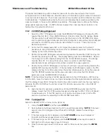
The ACU provides a means for driving each individual torque motor to test that motors
functionality. By driving each axis and observing the resulting motion of the antenna, a coarse
operational status of the motor and motor driver can be established.
1.
To manually drive the motors, select the
REMOTE COMMAND
window on the ACU:
2.
Using the
LEFT/RIGHT
and
UP/DOWN
arrow keys set the Remote Command value to
"
^0000
" and press
ENTER
.
3.
To drive the Cross Level motor, key in
^
1064,
^
1128 or
^
1192 and press
ENTER
to drive
the Cross Level axis LEFT, OFF or RIGHT respectively.
4.
To drive the Level motor, key in
^
2064,
^
2128 or
^
2192 and press
ENTER
to drive the
level axis FORWARD, OFF or BACKWARD respectively.
5.
To drive the Azimuth motor, key in
^
3064,
^
3128 or
^
3192 and press
ENTER
to drive
the azimuth axis CW, OFF or CCW.
7.3.7.
To Disable/Enable DishScan
To be able to use Step Track, or to revert to Conscan, as your active tracking mode you will have
to disable DishScan.
Select the
DISHSCAN
parameter window on the ACU:
1.
Press the RIGHT arrow, then press the UP arrow and last press the ENTER key to turn
DishScan mode ON.
2.
Press the RIGHT arrow, then press the DOWN arrow and last press the ENTER key to
turn DishScan Mode OFF.
If you change this remote parameter, you must save the change using REMOTE PARAMETERS.
If DishScan is
OFF
and the
Step Integral
parameter is set to
0000
, you will get a
constant
ERROR
0016
(DishScan error) and you will see
zeros
flashing in the lower left of the Azimuth
and Elevation ENTRY menu displays. This is a visual indication that DishScan is turned OFF.
7.3.8.
Satellite Reference Mode
The ships gyro compass input to the ACU may be accurate and stable in static conditions and
yet may NOT be accurate or stable enough in some underway dynamic conditions. If there is no
gyro compass or if the input is corrupt, not stable or not consistently accurate the tracking errors
will become large enough to cause the antenna to be mis-pointed off satellite.
Satellite Reference Mode will uncouple the gyro reference from the azimuth rate sensor control
loop. When operating in Satellite Reference Mode changes in ships gyro reading will not directly
affect the azimuth control loop. The Pedestal Control Unit will stabilize the antenna based
entirely on the azimuth rate sensor loop and the tracking information from DishScan. This will
keep the azimuth rate sensor position from eventually drifting away at a rate faster than the
tracking loop can correct by using the tracking errors to regulate the rate sensor bias.
Satellite Reference Mode can be used as a diagnostic mode to determine if tracking errors are
caused by faulty gyro inputs.
Satellite Reference Mode
MUST be used when:
•
No Gyro Compass is available
•
Frequent or constant ACU Error Code 0001 (Gyro Compass has failed)
•
Gyro Compass output is NMEA heading
•
Flux Gate Compass is being used
•
GPS Satellite Compass is being used
Summary of Contents for 4006-23 IN A 60" RADOME
Page 3: ......
Page 24: ...4006 23 Broadband At Sea Installation 4 6 This Page Intentionally Left Blank ...
Page 44: ...4006 23 Broadband At Sea Functional Testing 6 4 This Page Intentionally Left Blank ...
Page 64: ...4006 23 Broadband At Sea DRAWINGS 9 2 This Page Intentionally Left Blank ...
Page 66: ......
Page 69: ......
Page 75: ......
Page 77: ......
Page 78: ......
Page 79: ......
Page 83: ......
Page 85: ......
Page 87: ......

