Setup – Home Flag Offset
9711-44 Ku-Band TXRX
9-2
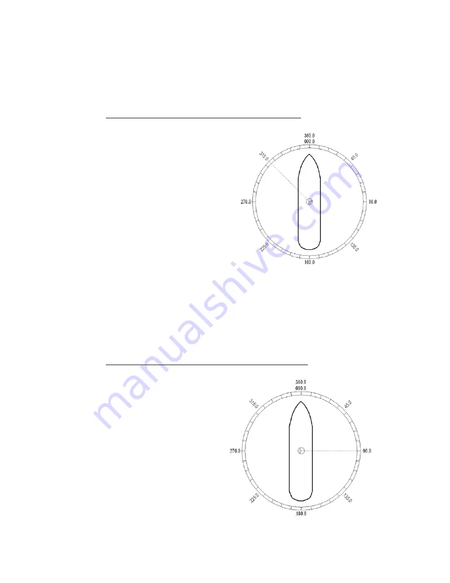
Figure 9-2 Antenna stopped before the Bow
Figure 9-3 Antenna stops past the Bow
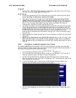
If AZ TRIM was a
plus
value: HFO = (TRIM / 360) x 255 Example: AZ TRIM was 0200 (plus 20 degrees). HFO
= (20/360) x 255 = (0.0556) x 255 = 14.16 round off to 14. Set, and Save, HFO to 014 using the “To Enter the
HFO value” procedure below.
If AZ TRIM was a
negative
value: HFO = ((360-TRIM) / 360)) x 255 Example: AZ TRIM = -0450 (minus 45
degrees). HFO = ((360 – 45) / 360)) x 255 = (315 / 360) x 255 = 0.875 x 255 = 223.125 round of to 223. Set,
and Save, HFO to 223 using the “To Enter the HFO value” procedure below.
9.1.2.
You Observe “Home” Pointing is LEFT of the Bow-line:
1.
In this example, I observe that the
Home position is short of the bow
line.
2.
I estimate that it is about 45 degrees.
3.
I target my desired satellite and
record the Calculated Azimuth to be
180.5.
4.
I drive UP (I estimated that I will need
to go UP about 45 degrees) and
finally find my desired satellite.
5.
Turn tracking ON to let the ACU peak
the signal up. When peaked, the
Azimuth is 227.0 degrees.
6.
I subtract Calculated from Peak (227
– 0180.5 = 46.5) and difference is
46.5 degrees.
7.
I can calculate what the correct value
for the Home position of the antenna
by subtracting (because “home” was
to the left of bow) this difference of 46.5 from the bow line position 360.0. Therefore “home”
should be 313.5 Relative.
8.
I now calculate the HFO = (313.5 / 360) x 255 = 0.87 x 255 = 222.06 which I round off to 222.
9.
I set, and Save, HFO to 222 using the “To Enter the HFO value” procedure below. After I re-initialize
the relative position of the antenna is now calibrated.
10.
If there is a small amount of error remaining, use AZ TRIM in the Optimizing Targeting procedure to
correct it.
9.1.3.
You Observe “Home” Pointing is RIGHT of the Bow-line:
1.
In this example, I observe that the
Home position is past the bow line.
2.
I estimate that it is about 90
degrees.
3.
I target my desired satellite and
record the Calculated Azimuth to
be 180.0.
4.
I drive DOWN (I estimated that I
will need to go
DOWN
about 89
degrees) and finally find my
desired satellite.
5.
Turn tracking ON to let the ACU
peak the signal up. When peaked,
the Azimuth is 90.0 degrees.
6.
I subtract Calculated from Peak
(180.0 – 90.0 = 90.0) and
difference is 90.0 degrees.
7.
I can calculate what the correct
value for the Home position of the
antenna by
adding
(because
Summary of Contents for 9711-44 KU-BAND TX/RX
Page 3: ......
Page 12: ...Table of Contents xii This Page Intentionally Left Blank ...
Page 24: ...Site Survey 9711 44 Ku Band TXRX 2 8 This Page Intentionally Left Blank ...
Page 64: ...Installation 144 Radome 9711 44 Ku Band TXRX 3 40 This Page Intentionally Left Blank ...
Page 112: ...Basic Setup of the ACU 9711 44 Ku Band TXRX 5 4 This Page Intentionally Left Blank ...
Page 114: ...Setup Ships Gyro Compass 9711 44 Ku Band TXRX 6 2 This Page Intentionally Left Blank ...
Page 116: ...Setup Band Select 9711 44 Ku Band TXRX 7 2 This Page Intentionally Left Blank ...
Page 122: ...Setup Home Flag Offset 9711 44 Ku Band TXRX 9 4 This Page Intentionally Left Blank ...
Page 130: ...Setup Searching 9711 44 Ku Band TXRX 11 6 This Page Intentionally Left Blank ...
Page 150: ...Antenna Specific Operation 9711 44 Ku Band TXRX 16 4 This Page Intentionally Left Blank ...
Page 154: ...Functional Testing 9711 44 Ku Band TXRX 17 4 This Page Intentionally Left Blank ...
Page 158: ...Installation Troubleshooting 9711 44 Ku Band TXRX 18 4 This Page Intentionally Left Blank ...
Page 180: ...Maintenance 9711 44 Ku Band TXRX 19 22 This Page Intentionally Left Blank ...
Page 198: ...Drawings 9711 44 Ku Band TXRX 23 2 This Page Intentionally Left Blank ...
Page 205: ......
Page 210: ......
Page 218: ......
Page 230: ......
Page 231: ......
Page 242: ......
Page 243: ......
Page 252: ......
Page 254: ......
Page 256: ......


