9797B-70 C-Band TXRX
Maintenance and Troubleshooting
7-11
7.3.10.
Satellite Reference Mode
The ships gyro compass input to the ACU may be accurate and stable in static conditions and yet may NOT
be accurate or stable enough in some underway dynamic conditions. If there is no gyro compass or if the
input is corrupt, not stable or not consistently accurate the tracking errors will become large enough to cause
the antenna to be mis-pointed off satellite.
Satellite Reference Mode will uncouple the gyro reference from the azimuth rate sensor control loop. This
decoupling of the Gyro source only happens 2.5 minutes after an azimuth command has been sent to the
antenna by means of an AZ target command, a search pattern initiated, or the a Satellites longitudinal
position is targeted. When operating in Satellite Reference Mode changes in ships gyro reading will reflect its
changes to the ACU’s display but will not directly affect the azimuth control loop. The Pedestal Control Unit
will stabilize the antenna based entirely on the azimuth rate sensor loop and the tracking information from
DishScan. This will keep the azimuth rate sensor position from eventually drifting away at a rate faster than
the tracking loop can correct by using the tracking errors to regulate the rate sensor bias.
Satellite Reference turned ON is the recommended standard mode of operation regardless of gyro type input.
To view, or change, the Satellite Reference Mode status, select the SAT REF remote parameter:
1.
Press the RIGHT arrow, then Press the UP arrow and then press ENTER to turn on
2.
Press the RIGHT arrow, the Press the DOWN arrow and then press ENTER to turn off.
NOTE:
If you change this remote parameter, you must save the change using REMOTE PARAMETERS.
7.3.11.
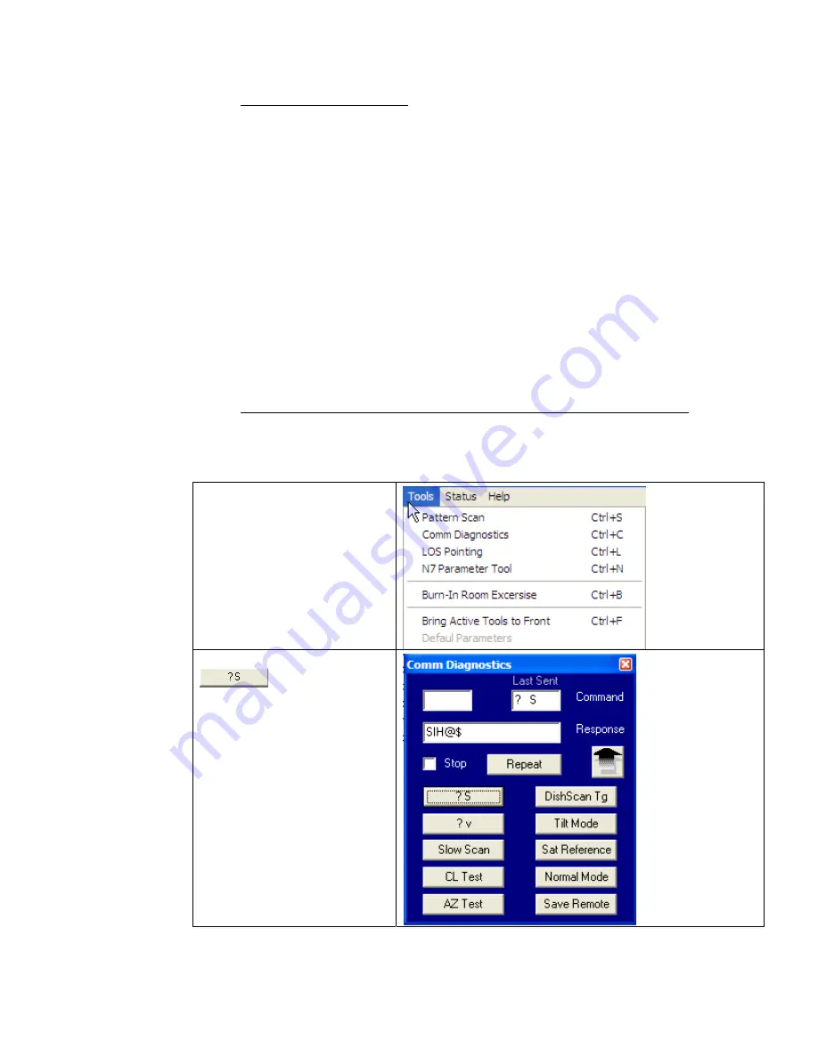
To Read/Decode an ACU Error Code 0008 (Pedestal Function Error):
An Error Code 8 as reported by the ACU is an indication that the above decks equipment has experienced an
error. One of the functions available within the “
Comm Diagnostics
” tool window provides the means to
read and decode the actual discreet Pedestal Function Error.
1.
Select the
“Comm
Diagnostics”
window
under to the Tools
submenu or Press “CTRL +
C”
Left mouse click on the
icon.
Summary of Contents for 9797B-70 C-Band TX/RX
Page 3: ......
Page 4: ......
Page 5: ......
Page 6: ......
Page 22: ...Basic System Information 9797B 70 C Band TXRX 3 8 This Page Intentionally Left Blank ...
Page 40: ...Setup 9797B 70 C Band TXRX 5 12 This Page Intentionally Left Blank ...
Page 66: ...Maintenance and Troubleshooting 9797B 70 C Band TXRX 7 24 This Page Intentionally Left Blank ...
Page 72: ...9797B 70 Technical Specifications 9797B 70 C Band TXRX 8 6 This Page Intentionally Left Blank ...
Page 74: ...Drawings 9797B 70 C Band TXRX 9 2 This Page Intentionally Left Blank ...
Page 76: ......
Page 79: ......
Page 81: ......
Page 82: ......
Page 84: ......
Page 85: ......
Page 87: ......
Page 88: ......
Page 90: ......
Page 98: ......
Page 100: ......
Page 101: ......
Page 106: ......
Page 108: ......
Page 110: ......


