Coastal 18 Ku-Band TVRO
Basic System Information
3-5
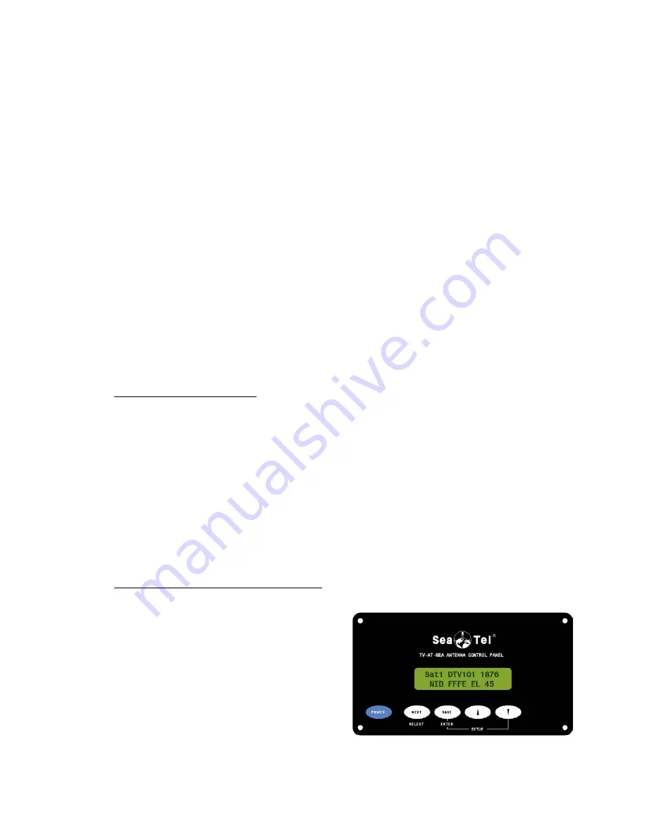
Figure 3-2 Antenna Control Panel
3.3. Components of the System Configuration
The following text provides a basic functional overview of the system components and component
interconnection as referred to in the System Block Diagram for your model antenna (refer to the appropriate
page which depicts your system configuration).
The system is comprised of two major sections: The Above-Decks Equipment (ADE) is comprised solely of
the antenna radome assembly which is mounted outside, on the boats’ upper deck or mast location chosen
for best satellite reception. The Below-Decks Equipment (BDE) includes a matrix switch, the antenna control
panel, satellite receiver(s), TV set(s) and all other ancillary equipment that is mounted in various locations
throughout the interior of the boat.
There will be an Antenna Control Cable between the ADE and BDE. This cable supplies the operating
voltage to the antenna and allows you to setup and operate the antenna from the Antenna Control Panel.
The panel also constantly displays the status of the antenna.
Coax cables between the ADE and BDE provide the received satellite signals from the antenna to the matrix
switch. The matrix switch then distributes these satellite signals to the satellite receiver. The satellite
receivers convert the satellite signals to provide audio and video to your television and/or stereo.
You will need to have 4 coaxes between the ADE and BDE if you intend to have a Quad (4 output) LNB
installed on your antenna at any point in time. Usage of this LNB is very popular in Europe.
If you will only have a dual output LNB installed (linear or circular) you will only need to have 2 coaxes
between the ADE and BDE.
Unused coax connections in the radome MUST be terminated (75 ohm
terminators) if not used.
3.3.1. Antenna Assembly
The antenna radome assembly consists of a satellite antenna and a linear, or circular, Low Noise Block
converter (LNB) with polarization motor mounted on a stabilized antenna pedestal, housed inside a
radome. The radome provides an environmental enclosure for the antenna pedestal assembly inside it.
This keeps wind, water condensation and salt-water spray off the antenna pedestal assembly. This
prevents damage and corrosion that would shorten the expected life span of the equipment.
The antenna control cable is connected between the antenna radome assembly and the antenna control
panel. This cable provides DC voltage to the antenna and all control signals to and from the antenna.
Two, or Four, RG-6 (or better) coax cables are connected from the antenna radome assembly to the
below decks equipment. These cables carry the intermediate frequency (950-2150MHz) signals from the
antenna assembly directly to a matrix switch (depending on the configuration), and provide DC voltage
and tone switching to the LNB mounted on the antenna. These cables ultimately provide the input signal
into the satellite receiver(s) from the matrix switch.
3.3.2. Display Antenna Control Panel
The antenna control panel allows the
operator to control and monitor the
antenna pedestal with simple dedicated
function buttons, LED’s and a 2 line
display. The control panel can be
surface mounted to any convenient panel
location. It is recommended that the
antenna control panel be mounted near
one of the television locations where you
can see the television screen while you
are controlling the antenna.
The antenna control panel is connected
to the antenna and to the +12 VDC
power supply.
Summary of Contents for COASTAL 18
Page 3: ......
Page 8: ...Table of Contents viii This Page Intentionally Left Blank ...
Page 30: ...Installation Coastal 18 Ku Band TVRO 4 8 This Page Intentionally Left Blank ...
Page 42: ...Setup Coastal 18 Ku Band TVRO 5 12 Figure 5 3 Display Antenna Control Panel Setup Mode page 1 ...
Page 43: ...Coastal 18 Ku Band TVRO Setup 5 13 Figure 5 4 Display Antenna Control Panel Setup Mode page 2 ...
Page 44: ...Setup Coastal 18 Ku Band TVRO 5 14 Figure 5 5 Display Antenna Control Panel Setup Mode page 3 ...
Page 45: ...Coastal 18 Ku Band TVRO Setup 5 15 Figure 5 6 Display Antenna Control Panel Setup Mode page 4 ...
Page 46: ...Setup Coastal 18 Ku Band TVRO 5 16 Figure 5 7 Display Antenna Control Panel Setup Mode page 5 ...
Page 54: ...Maintenance Coastal 18 Ku Band TVRO 6 8 This Page Intentionally Left Blank ...
Page 60: ......
Page 64: ...Computer Interface Coastal 18 Ku Band TVRO 8 4 This page left blank intentionally ...
Page 66: ...Drawings Coastal 18 Ku Band TVRO 9 2 This page left blank intentionally ...
Page 75: ......
Page 76: ......
Page 77: ......


