Installation
ST94-21 C/Ku-Band TVRO
3-22
2.
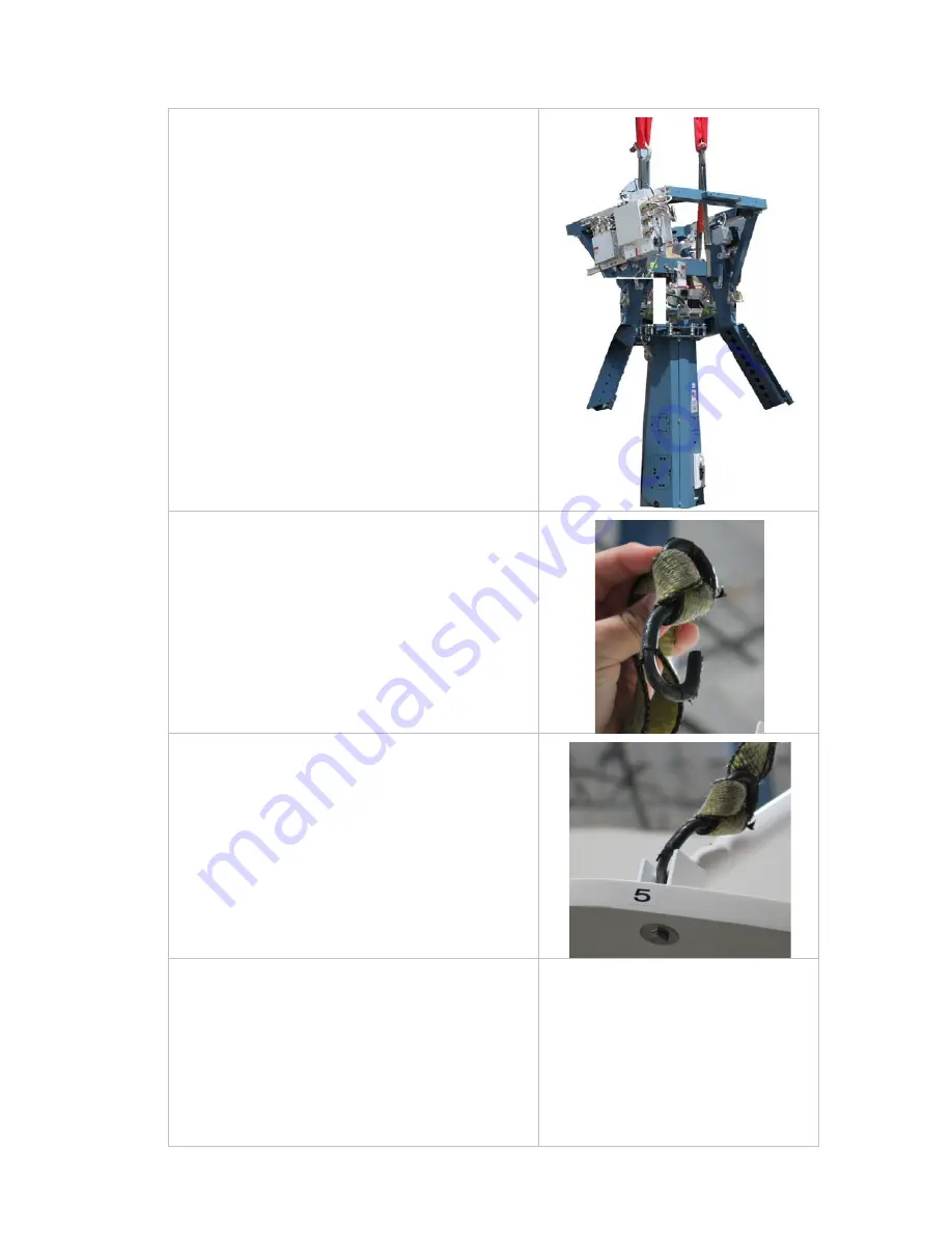
Using a crane, or other suitable lifting apparatus,
lift the pedestal up and onto the stand which
was installed in step 1.
NOTE: The circuit breaker panel should be
oriented to be facing the radome entry hatch
(AFT) so that it is within easy reach for powering
the equipment OFF.
3.
Install the pedestal mounting hardware. Apply
Loctite and tighten these bolts to torque spec.
4.
Stow the pedestal, at zenith, using the stow
brace kit provided with the antenna system
(refer to the stow procedure in the maintenance
chapter of this manual.
5.
Attach two small S-hooks to two web lifting
straps.
6.
Hook the two lifting strap S-hooks into the end
of the tubing of the left & right feed struts.
7.
Unbolt the reflector from the raised platform of
the Baseframe & Reflector crate.
8.
Using a crane, or other suitable lifting apparatus,
lift the reflector up and onto the reflector
mounting brace of the pedestal.
9.
Assure that the reflector is orientated such that
the numbered labels on the back frame of the
dish and the reflector mounting brace align.
10.
Install the reflector onto the reflector mounting
brace using the hardware provided. Apply
Loctite to and tighten the mounting bolts.
11.
Disconnect the S-hooks from the feed struts.
EAR Controlled - ECCN EAR99
Summary of Contents for ST94-21
Page 4: ...EAR Controlled ECCN EAR99 ...
Page 10: ...Table of Contents x This Page Intentionally Left Blank EAR Controlled ECCN EAR99 ...
Page 123: ...EAR Controlled ECCN EAR99 ...
Page 126: ...EAR Controlled ECCN EAR99 ...
Page 139: ...EAR Controlled ECCN EAR99 ...
Page 140: ...EAR Controlled ECCN EAR99 ...
Page 141: ...EAR Controlled ECCN EAR99 ...


