Fig. 36
Fig. 37
1
2
3
4
10
5
6
7
8
9
Fig. 38
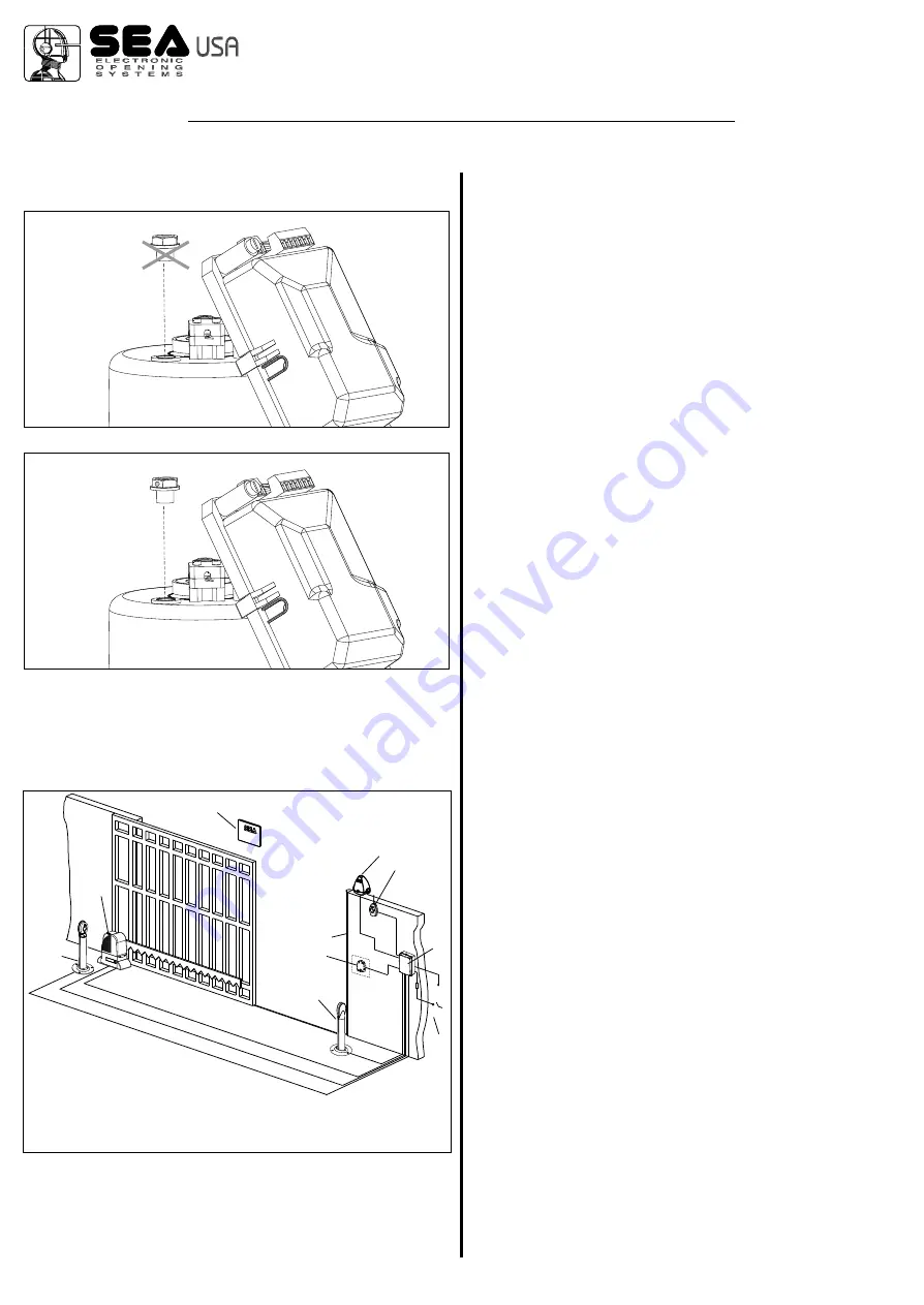
13. BREATHER SCREW REPLACEMENT
Replace the breather screw before startup.
14.
(Fig. 38)
CABLE LAYOUT
1) LEPUS operator
2) Left photocell
3) Right photocell
4) Pneumatic safety edge
5) Key switch
6) Flashing warning lamp
7) Radio receiver
8) Warning notice
9) Electronic control unit or j
10) Differential switch
unction box
Cod. 67410022
REV 00 - 12/2013
®
International registered trademark n. 2.777.971
MECHANICAL INSTALLATION
10


