Cod. 67410022
115 V (±5%) 50/60 Hz
350W
70
60%
1550 rpm
1/30
-4°F +131°F
130°C
33 pound
1,75 L.
IP 55
0,65 feet/s
0,75 feet /s
60 Nm
1000 Kg / 2204,62 pound
~
µF
Mechanical in oil bath - Electronic
Mechanical with leve/Inductive
LEPUS 1000 110V
1000 Kg
2204,62 pound
L
E
P
U
S
1
0
0
0
1
1
0
V
60%
TECHNICAL DATA
Power Supply
Power
Motor rotation speed
Reduction ratio
Room temperature
Thermal protection intervention
Weight of the unit with oil
Oil quantity
Protection rating
Gate speed (pinion Z16)
Gate speed (pinion Z20)
Maximum weight of the gate
Limit switch
Motor capacitor
Working frequency
Maximum torque
Anti- crushing clutch
Note
: The frequency of use is valid only for the first hour at 68°F room
temperature.
LEPUS MOTOR-REDUCER USING-GRAPHIC
F
re
q
u
e
n
c
y
o
f
u
s
e
M
a
x
g
a
te
w
e
ig
h
t
Oil-bathed motor-reducers
REV 00 - 12/2013
L
E
P
U
S
1
0
0
0
1
1
0
V
®
International registered trademark n. 2.777.971
LEPUS
is an
oil-bathed motor-reducer
created for sliding
gates automation. The motor-reducer
irreversibility
allows a
perfect and safe gate closing avoiding the setup of an
electrolock and in case of power supply lacking, the release
device which is in the frontal part of the motor-reducer allows the
manual opening and closing. The operator has a
mechanical
adjustable clutch
which ensures the control of the gate
pushing. Moreover,
the electronic reversing device
realized
through an
encoder
makes the lepus motor-reducer a safe and
reliable operator allowing in a simple way to comply with the
current norms in the countries where this product is set up.
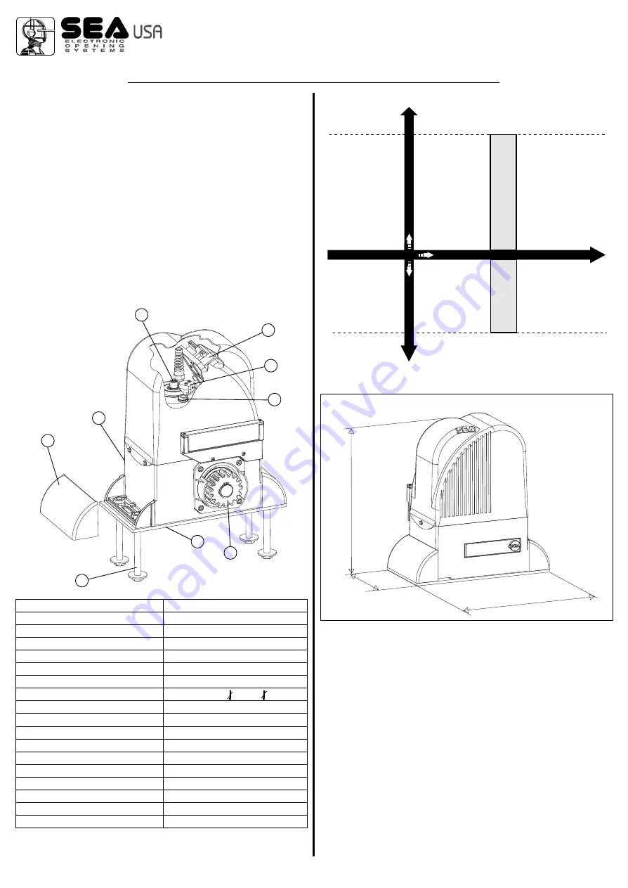
1
Adjustable Foundation plate
2
Anchor bolts
3
Angular cover
4
Pinion
5
Lever release reducer
6
Adjusting screw mechanical clutch
7
Electronic control unit
8
Oil filling up cap
9
Magnetic encoder
MAIN PARTS NOMENCLATURE
1
1
2
2
3
3
4
4
5
5
6
6
7
7
8
8
9
9
1. GATE ARRANGEMENT
The first thing to check is that the gate is in good running order as
follows:
a) The gate is rigid and straight and runs smoothly throughout its
travel.
b) that the inferior sliding guide-rail is perfectly straight and
horizontal to avoid a derailment of the gate (fig. 1); furthermore it
must be free of irregularities and foreign bodies which could
obstruct the normal run of the gate (fig. 2 and 3).
c) that the upper guides are not fixed (fig. 4) but furnished with
rollers which allow the sliding of the gate without difficulties (fig. 5
and 6).
d) that the distance between the end of the gate ( in maximum
opening position) and the eventual wall must be at least of 5
inches (fig. 7).
e) The lower support wheels have sealed bearings or grease
MECHANICAL INSTALLATION
4
1
,
8
3
6
12,79
29
6,
DIMENSIONS (inches)


