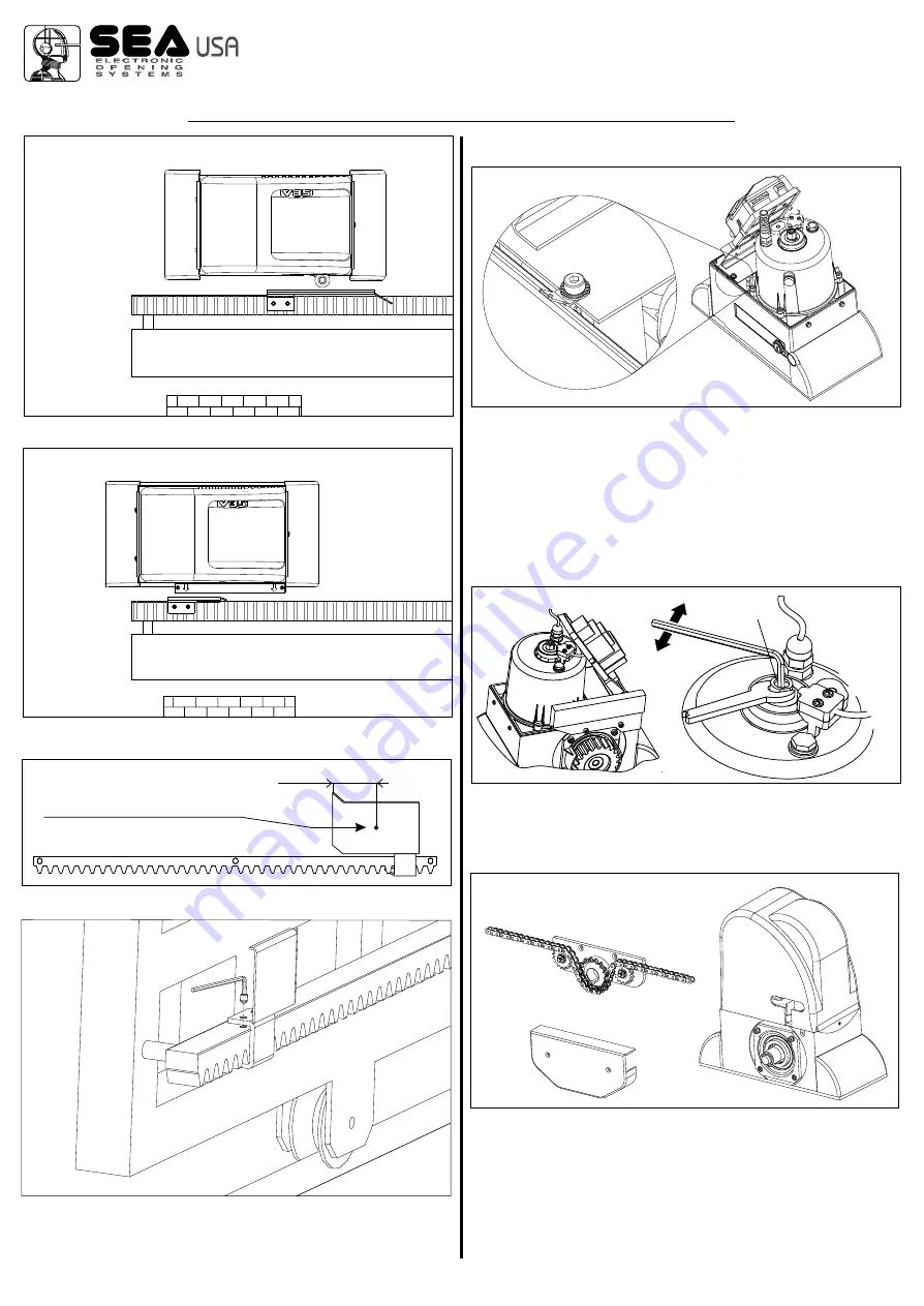
Through the braking trimmer adjustment placed on the electronic
control unit it is possible to stop the gate in the point desidered.
9. GROUNDING (Fig. 27)
10. CLUTCH ADJUSTMENT
10.1.
Take power supply tension off.
10.2.
To adjust the clutch act as follows:
- Act on the “A” screw (Fig. 28) in the following way:
- Clockwise = less clutch sensibility and more pushing force
- Anti-clockwise = more clutch sensibility and less pushing force
Fig. 23
Fig. 24
A
A
Fig. 28
Fig. 26
1,96 in.
X
Fig. 25
Fig. 27
Fig. 29
Mechanical limit switch
Inductive limit switch
Place where the wheel (mechanical
limit switch) or the arrow (inductive
limit switch) must be
11. ASSEMBLING OF THE CHAIN SYSTEM
The assembling of the main parts which include the whole chain
automation is illustrated in Fig.29.
In the pictures 30 and 31 it is possible to see the correct
installation with opened and closed gate respectively; notice the
obliged run of the chain inside the pinion group which must not be
modified.
For a correct installation follow carefully the indications written
below:
11.1.
Weld two strong pierced brackets to the two extremities of
the gate to couple the chain.
Cod. 67410022
REV 00 - 12/2013
®
International registered trademark n. 2.777.971
MECHANICAL INSTALLATION
8


