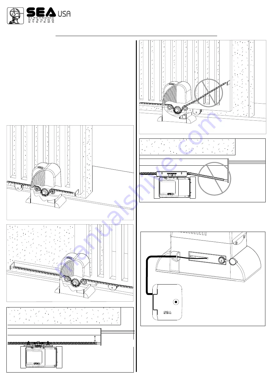
Notice: the holes for the chain tensioner and so the chain
itself must be to a minimum distance of 1,77 in. from the
gate (Fig.32).
11.2.
Install the chain making it pass through the pinion group as
in Fig.29.
The chain must be always in line both vertically (Fig.30) and
orizontally (Fig.32), if not perfectly aligned (Fig.33 and 34) it may
derail from the pinion group or the motor reducer risks a greater
effort not allowing the right operating of the system.
11.3.
Set up a fillet chain tensioner to the two extremities of the
gate to regulate the tension of the chain.
Notice: do this last operation with the engine completely
unlocked through the special unlocking key.
Fig. 34
Fig. 32
1,77 in.
Fig. 30
Fig. 33
Fig. 31
Fig. 35
12. EXTERNAL RELEASE (OPTIONAL)
Security
box
Cod. 67410022
REV 00 - 12/2013
®
International registered trademark n. 2.777.971
MECHANICAL INSTALLATION
9


