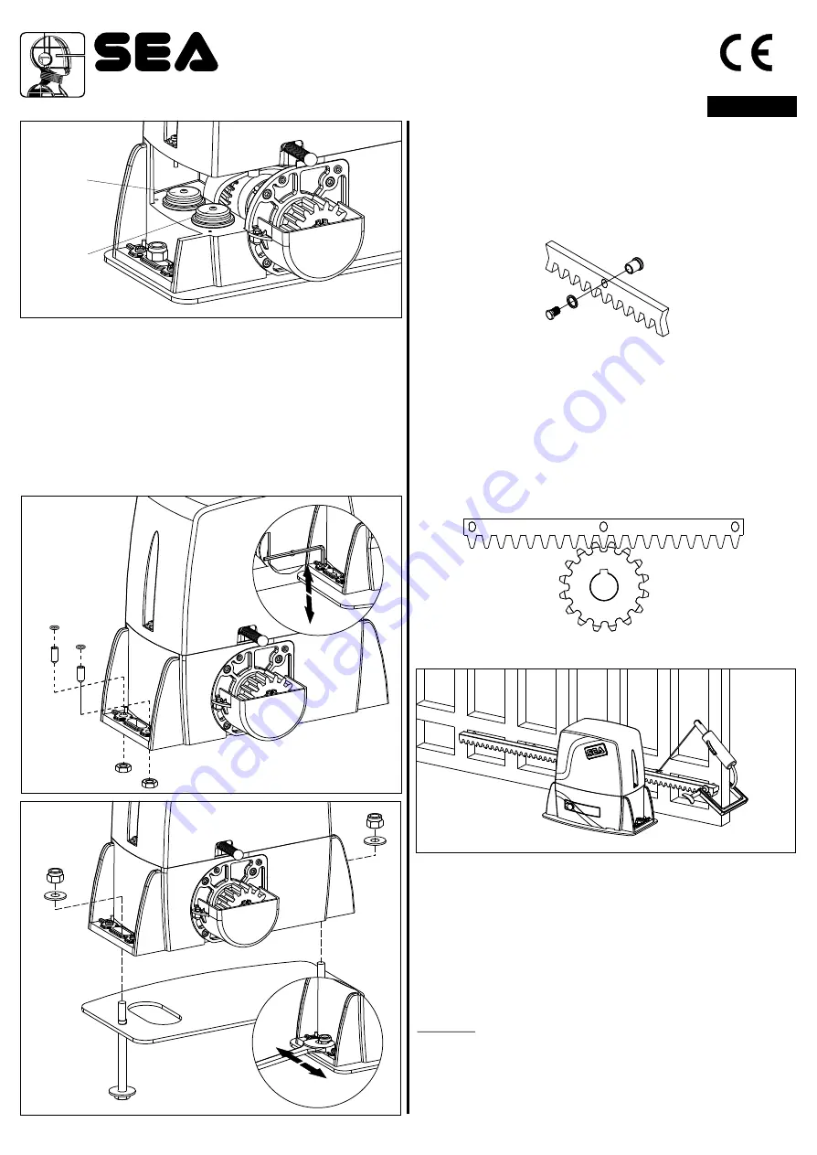
Fig. 3
4. FITTING OF THE MOTOR REDUCER
4.1.
Insert the 4 grains into the special holes, so that it is possible to
adjust the motor reducer height on the plate (Fig. 4).
At the end of installation check if the 4 crub screws are well
gripped on the foundation plate.
4.2.
Fix the motor reducer to the foundation plate with the 2 included
nuts, adjusting the side position (Fig. 5) so to respect the shown quota
in (Fig. 2).
4.3. Remove the closing loading oil cap (red) and substitute it with
that supplied apart provided with the airhole (black).
Hole 1
Hole 2
Fig. 4
Fig. 5
5. GEAR RACK MOUNTING
5.1.
Release the motor and open the leaf completely;
5.2.
Fix on each gear rack element the support pawls with the
appropriate lock screws, make sure to put them in the upper part
of the hole (Fig. 6) ;
5.3.
Lean the gear rack element on the toothed pinion of the
motor in parallel to the ground slideway of the gate, as shown in
Fig. 7 and electrically weld the central pawl B to the gate
structure (Fig. 8).
Manually move the gate until pawl C is placed corresponding to
the pinion and fix it through electric welding. Repeat the same
procedure for pawl A after having placed it corresponding to the
pinion;
5.4.
Make sure that all the gear rack elements are perfectly
aligned and placed correctly (teeth in phase). It’s suggested to
place two aligned elements in front of a third one as shown in
Fig.9;
5.5.
Repeat the above described operation for all the remaining
gear rack elements which have to be installed;
5.6.
To avoid that the door weights down on the pinion (Fig.10)
lift up the whole rack about 1,5 mm.
Warning
: Keep a gap of about 0,5 mm between pinion tooth
and gear rack tooth;
5.7.
Make sure that the gear rack works at the center of the
pinion along all rack elements, if necessary, adjust the length of
the spacers.
Fig. 7
A
B
C
Fig. 6
Fig. 8
Sistemi Elettronici
di Apertura Porte e Cancelli
International registered trademark n. 804888
®
cod. 67410324
ENGLISH
11
REV 07 - 12/2015


