background image

Sistemi Elettronici

di Apertura Porte e Cancelli

International registered trademark n. 804888

®

Fig. 25

2x ,5

1

2x1,5

x

3 1,5

1x ,15

2 1,5

x

3x1,5

1

3x ,5

6x1,5

1

8x ,5

1

2

3

4

10

5

6

7

8

9

Fig. 24

Fig. 26

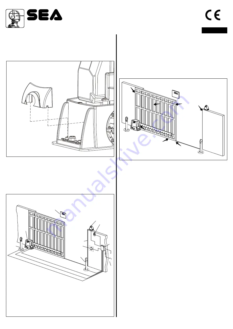
10. SCREW COVER  MOUNTING

At the end of the mechanical installation and after having 
executed all the required adjustments, mount the two screw 
covers on the operator as shown in Fig. 24.

11. ELECTRIC CONNECTIONS OF THE 
INSTALLATION (Fig. 25)

2

The cable mesures are indicated in mm

1) Saturn - Boxer
2) Photocell Sx 
3) Photocell Dx
4) Mechanical safety edge
5) Key push botton

6) Flasher
7) Receiver 
8) Warning notice 
9) Junction box 
10) Differential 16A - 30mA

Ex. 230V version with integrated electronic control unit 

12. RISK EXAMINATION

The points pointed by arrows in Fig. 26 are potentially 
dangerous. The installer must take a thorough risk examination 
to prevent crushing, conveying, cutting, grappling, trapping so 
as to guarantee a safe installation for people, things and animals 
(

)

Re. Laws in force in the country where the installation has been 

made.

13.  NOTICE

SEA can not be deemed responsible for any damage or accident 
caused by product breaking, being damages or accidents due to 
a failure to comply with the instructions herein. The guarantee 
will be void and the manufacturer responsibility (according to 
Machine Law) will be nullified if SEA original spare parts are not 
being used.

This is a quotation from the GENERAL 

DIRECTIONS that the installer must read carefully before 
installing. Packaging materials such as plastic bags, foam 
polystyrene, nails etc must be kept out of children’s reach as 
dangers may arise. 

The electrical installation shall be carried out by a professional 
technician who will release documentation as requested by the 
laws in force. 

14. 

15. 

SAFETY PRECAUTIONS:

All electrical work and the choice of the operating logic should 
conform to   current regulations. A 16 A   0,030 A differential 
switch must be incorporated into the source of the operators 
main electrical supply and the entire system properly earth 
bonded. Always run mains carrying cables in separate ducts to 
low voltage control cables to prevent mains interference.

SPARE PARTS:

To obtain spare parts contact:

SEA S.p.A. -Zona Ind.le, 64020 S. ATTO   Teramo   Italia

ENGLISH

14

cod. 67410324

REV 07 - 12/2015

Summary of Contents for Boxer 1000

Page 1: ...rademark n 804888 cod 67410324 MOTORIDUTTORI PER CANCELLI SCORREVOLI MOTOR REDUCERS FOR SLIDING GATES MOTEURS POUR PORTAILS COULISSANTS MOTOREDUCTORES PARA CANCELAS CORREDIZAS BOXER 1000 2000 2000 Threephase REV 07 12 2015 SATURN 600 1000 2000 230V 115V 1500 24V 230V 115V 1200 24V FAST 500 SUPER FAST 24V 230V ...

Page 2: ...ree Pinion Z16 Z20 speed Maximum torque Gate maximum weight Gate maximum length Mechanical clutch Limit switch TECHNICAL DATA Power supply Power Absorbed current Motor capacitor Working frequency Working Temperature Thermoprotection Weight Anticrushing clutch Protection degree Pinion Z16 Z20 speed Maximum torque Gate maximum weight Gate maximum length Mechanical clutch Limit switch Note The freque...

Page 3: ...n the plate make sure that it is perfelcty leveled and that the distance of 58 67 mm as shown in Fig 2 is respected Before cementing the plate insert a flexible plastic duct of at least 30mm in diameter into the special hole of the plate 2 FOUNDATION PLATEANCHORAGE To install the foundation plate it is necessary to 2 1 Prepare a concret basement with the dimensions shown in Fig 1 where the foundat...

Page 4: ...ay of the gate as shown in Fig 7 and electrically weld the central pawl B to the gate structure Fig 8 Manually move the gate until pawl C is placed corresponding to the pinion and fix it through electric welding Repeat the same procedure for pawlAafter having placed it corresponding to the pinion 5 4 Make sure that all the gear rack elements are perfectly aligned and placed correctly teeth in phas...

Page 5: ...ow mentioned instructions Fig 11 Take the gate to complete closing Place the small plate on the gear rack so that the limit switch is in corrispondence of pointX which is placed 50 mm from the folded side of the small plate Fig 14 and fix it with the delivered screws Fig 15 Fig 16 Limit switch in closing Limit switch in opening 1 5 mm Fig 10 Fig 11 Fig 12 Mechanical limit switch Adjusting the trim...

Page 6: ...rn 24V 9 CLUTCHADJUSTMENT Where present 9 1 Switch off electric power 9 2 In order to adjust the clutch it is necessary to Act on the scrub screw A Fig 23 as follows Turning clockwise less clutch sensibility more thrust force Counter clockwise more clutch sensibility less thrust force Ex Boxer power sensibility power sensibility Steel rack Plastic rack Sliding gate Magnet Limit sheet Rack Pinion E...

Page 7: ...e 13 NOTICE SEAcan not be deemed responsible for any damage or accident caused by product breaking being damages or accidents due to a failure to comply with the instructions herein The guarantee will be void and the manufacturer responsibility according to Machine Law will be nullified if SEA original spare parts are not being used This is a quotation from the GENERAL DIRECTIONS that the installe...

Page 8: ... 1 5 mm Check the usury status of pinion and gear rack Check the fixing screws Check the connection cables integrity Check limit switch functionality and status in opening and closing and the related small plates Annual 4 years Annual Annual Annual Annual Annual Annual Annual 18 RELEASE SYSTEM FOR SATURN AND BOXER 18 1 In order to release do as follows Open the lock cover insert the key and rotate...

Page 9: ...ection Vitesse pignon Z16 Z20 Couple max Poids Max du portail Longueur Max du portail Friction Mécanique Fin de course DONNEES TECNIQUES Alimentation Puissance Courant absorbé Condensateur de décollage Fréquence d utilisation Temperature ambiante Intervention de Thermoprotection Poids Friction anti écrasement Dégré de protection Vitesse pignon Z16 Z20 Couple max Poids Max du portail Longueur Max d...

Reviews: