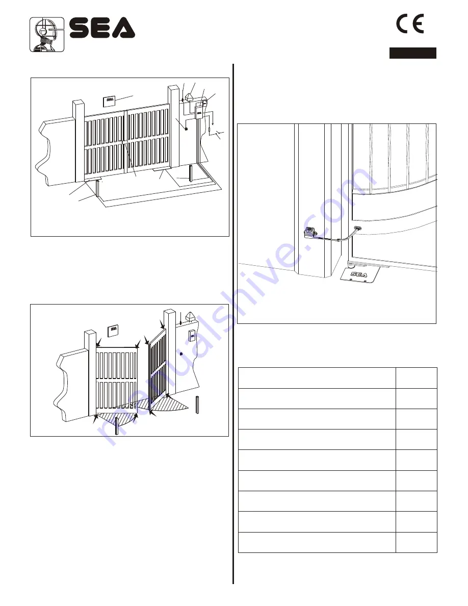
Fig. 34
Fig. 35
4 1 5
X ,
4X1,5
5
2X1,
X ,
1
3
5
2
X
1
,5
3
,5
X1
X1 5
3
,
X1 5
1
,
2
,
X1 5
x
5
1 RG 8
1
2
3
4
2
5
6
7
8
9
10
11
Fig. 36
ENGLISH
11. CABLE LAYOUT (Fig. 34)
1) Warning notice
2) Compact operator
3) Left photocell
4) Right photocell
8) Electronic control unit
9) Receiver
10) 16A-30mA differential switch
11) Electric lock (SB version only)
5) Key switch
6) Antenna
7) Flashing warning lamp
12. RISK EXAMINATION
The points pointed by arrows in Fig. 35 are potentially
dangerous. The installer must take a thorough risk examination
to prevent crushing, conveying, cutting, grappling, trapping so
as to guarantee a safe installation for people, things and animals
(
).
Re. Laws in force in the country where installation has been
made.
NOTICE
As for misunderstandings that may arise refer to your area distributor or call
our help desk. These instructions are part of the device and must be kept in
a well known place. The installer shall follow the provided instructions
thoroughly. SEA products must only be used to automate doors, gates and
wings. Any initiative taken without SEA Srl explicit authorization will
preserve the manufacturer from whatsoever responsibility. The installer
shall provide warning notices on not assessable further risks. SEA s.r.l. in
its relentless aim to improve the products, is allowed to make whatsoever
adjustment without giving notice. This doesn’t oblige Sea to up-grade the
past production. SEA s.r.l can not be deemed responsible for any damage
or accident caused by product breaking, being damages or accidents due
to a failure to comply with the instructions herein. The guarantee will be
void and the manufacturer responsibility (according to Machine Law) will
be nullified if SEA Srl original spare parts are not being used.
This is a
quotation from the GENERAL DIRECTIONS that the installer must read
carefully before installing. Packaging materials such as plastic bags, foam
polystyrene, nails etc must be kept out of children’s reach as dangers may
arise.
The electrical installation shall be carried out by a professional technician
who will release documentation as requested by the laws in force.
SAFETY GATE
For a correct and safe installation it is strongly recommended to
install a Safety Gate,
which allows the fulfilment of the force
diagram included in the norm EN 12453
and consequently the
test and start of the whole installation.
PERIODICAL MAINTENANCE
Check the oil level
(Trasparent cap n.7 in Fig. 1)
Change the oil
Verify the functionality of the by-pass valves
(check the force in opening and closing)
Check the release function
Verify the slowdown regulation (where present)
Check the correct drain of the rainwater
Check the integrity of the connection cables
Grease all the moving parts
Grease the rotation axis of the box as in Fig.31
Annual
4 years
Annual
Annual
Annual
Annual
Annual
Annual
Annual
All the above described operations must be made exclusively by
an authorized installer.
67410850
Sistemi Elettronici
di Apertura Porte e Cancelli
International registered trademark n. 804888
®
REV 04 - 01/2010
16


