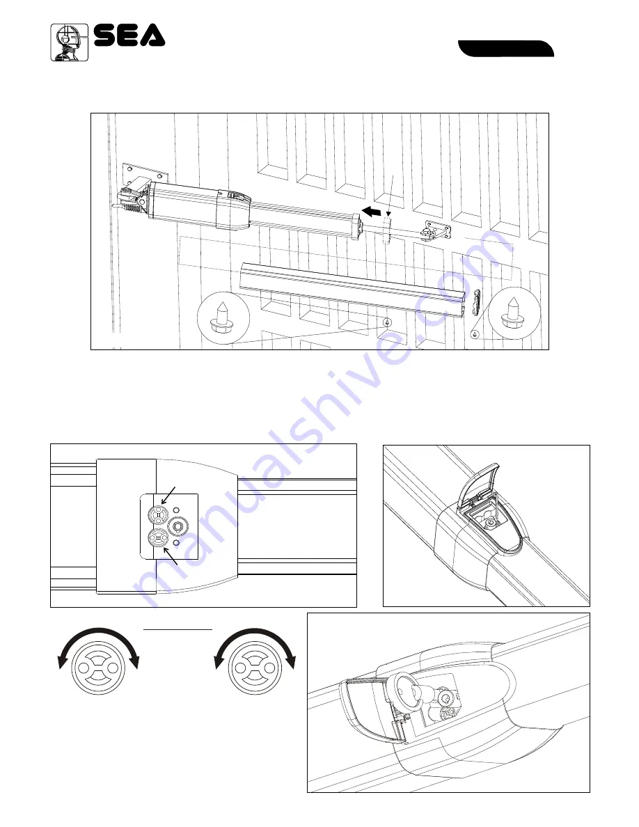
Fig. 28
Fig. 29
Fig. 27
A
A
INSTALLATION OF THE CHROMIUM-PLATED ROD PROTECTION
TORQUE ADJUSTMENT (By-Pass Valves)
In case of first installation both, the cover of the release and the cover of the by pass valves must not yet be inserted.
In this case refer to fig. 27 and fig.29.
Should the by-pass valves adjustment be made in a second moment, because of periodical maintenance or other,
take off the screw which locks the by-pass cover (fig. 28), take off the by-pass cover and adjust the pressure of the by-
pass valves with the special key given to the installer free of charge (Fig. 29).
Make sure to have inserted the antivibration plastic frame (
A
) before inserting the rod cover extrusion (Fig. 26).
Up
Grey
(Opening)
Yellow
(Closing)
+
-
+
-
Grey
n
e t
m
t
s
in
u
o
j
d
p
a
e
n
e
c
in
r
g
o
F
Yellow
By-Pass Valves
n
me
t
s
t in
u
j
c
d
l
a
o
e
s
c
i
r
n
o
g
F
Regulate the opening and closing forces of the gate
respecting the force diagram (included in the
En12453 normative); the thrust force however must
not be superior then 15kgF.
Sistemi Elettronici
di Apertura Porte e Cancelli
International registered trademark n. 804888
®
27
67411170
Fig. 26
HALF TANK - MINI TANK
English
English
REV 06 - 03/2015
Summary of Contents for HALF TANK
Page 22: ......


