background image

INSTALLATION WARNINGS

• For gate operators: install only when

A. The operator is appropriate for the gate’s construction and usage Class.
B. All opening spaces on the wall of the horizontal slide gate are guarded or screened from the bottom of the gate to a minimum of 4 
feet (1m) above the ground so that it could be possible to keep on the entire surface of the wall a minimum distance of 2-1/4 (57,15mm) inches from the 
gate and the wall on which the gate runs.
C. All exposed pinch points are eliminated or guarded
D. Guarding is supplied for exposed rollers.
E. Check if the gate works freely in both directions before installing the gate operator system. Any necessary repair to the gate must be done 
before installing the equipment. Swinging gate shall not open into public access areas.

• The operator systems must be installed in a proper place to prevent contacts with adjacent structures in opening and closing. Watch out to install the system so 
that users could have full view of the area.
• For operators using non-contact sensors:

A. See instructions on the placement of non-contact sensors for each Type of application.
B. Watch out to reduce the risk of nuisance tripping of the sensor.
C. One or more non-contact sensors shall be located where the risk of entrapment or obstruction exists, such as the perimeter reachable by a moving 
gate or barrier.

• For operators utilizing contact sensors:

A. One or more contact sensors must be located where the risk of entrapment or obstruction exists, such as the operators’ edges. They 
should be installed both inside and outside the operator’s edge.
B. A hardwired contact sensor must be installed, watching out to arrange its wiring so that the communication between the sensor and the 
operator should not be subjected to mechanical damage.
C. A wireless contact sensor such as a radio frequency (RF) signal transmitter must be located where the signal’s transmission cannot be 
obstructed by structures or natural landscaping.

• Controls should be far enough from the gate or barrier so that the user is prevented from coming in contact with them while operating the controls. Controls are 
intended to be used to reset an operator after 2 sequential activations of the entrapment protection device and must be located in the line-of-sight of the outdoor. 
Install a security feature If controls are easily accessible, to prevent unauthorized use.

AFTER INSTALLATION

• Check that: the open and close force are properly adjusted; the piston does not bottom out in either direction, the breather screws have been removed, the 
positive stops used are sufficient for stopping the gate properly, all the pinch points and potential entrapment areas are reduced.
• Check and test all reversing devices.
• The installer should instruct user on the operator system’s proper operation. They should together review the basic functions of the reversing devices and how to 
periodically test them. Reversing devices include one or more of the followings: reversing loops, photocells, reversing edges, etc. The installer has to instruct 
user on how to remove the operator system from service, on shutting power off on the service panel and how to use the operator system manually.

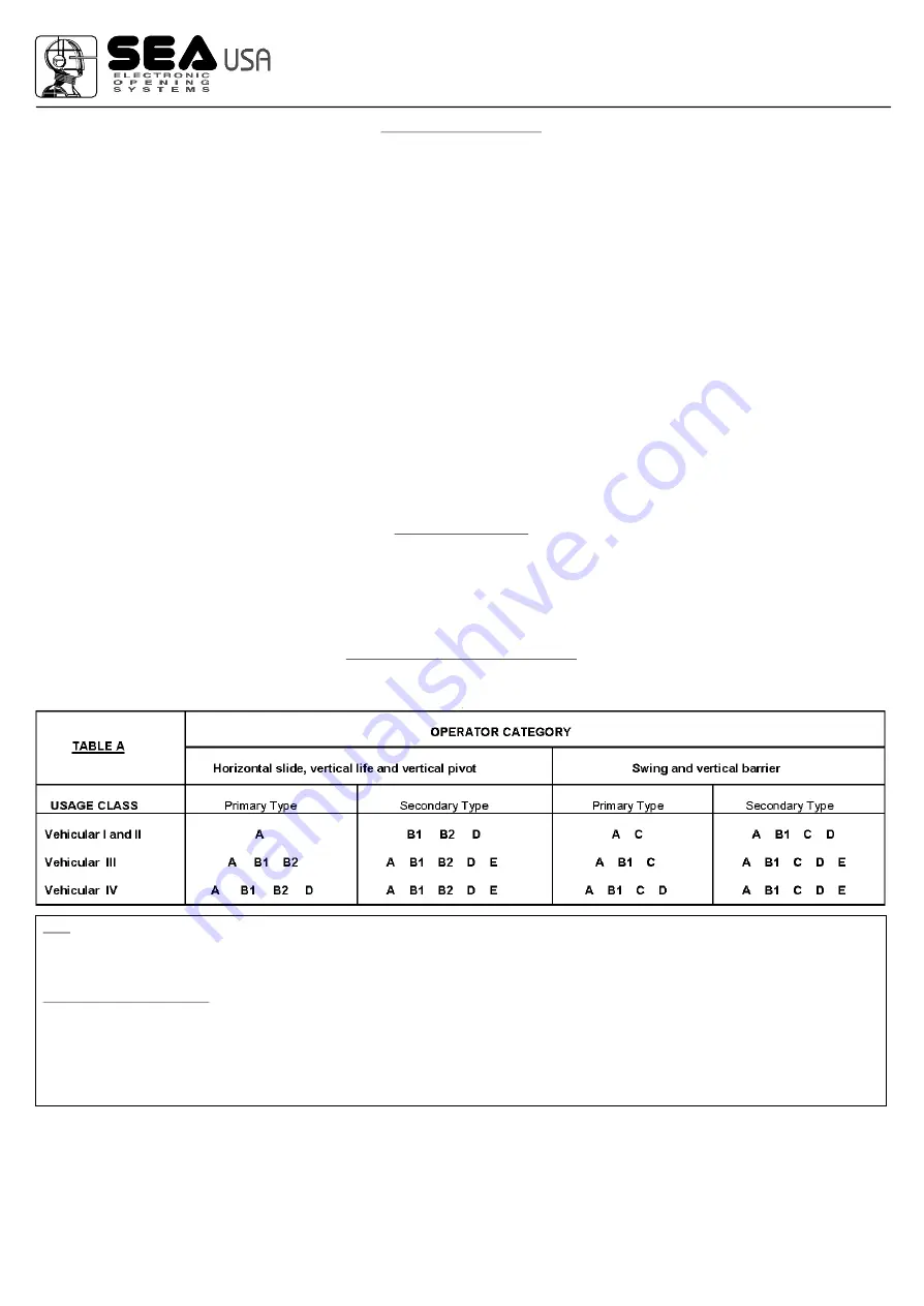
GENERAL ENTRAPMENT PROVISIONS

A vehicular operator must be installed with one independent primary and one independent secondary means at least to protect against entrapment 
(see Table A):

Note

: The same type of device shall not be utilized for both the primary and secondary entrapment protection means. The use of a single device to cover both 

the opening and closing directions is in accordance with the requirements; however, a single device is not required to cover both directions. A combination of 
one Type B1 for one direction and one Type B2 for the other direction is the equivalent of one device, for the purpose of complying with the requirements of 
either the primary or secondary entrapment protection means.

Entrapment protection types

Type A: 

Inherent entrapment sensing system.

Type B1:  Provision for connection of a non-contact sensor (photoelectric or equivalent).
Type B2:  Provision for connection of a contact sensor (edge device or equivalent).
Type C: 

Inherent adjustable clutch or pressure relief device.

Type D: 

Provision for connection of an actuating device requiring continuous pressure to maintain opening or closing motion of the gate.

Type E:

 An inherent audio alarm.

CLASS OF OPERATORS

RESIDENTIAL VEHICULAR GATE OPERATOR - CLASS I - A vehicular operator (or system) intended for use in a home of one-to four, single-family dwelling, or 
a garage or parking area associated therewith.

COMMERCIAL/GENERAL ACCESS VEHICULAR OPERATOR - CLASS II - A vehicular operator (or system) intended for use in a commercial location or 
building such as multi-family housing unit (five or more single family units), hotel, garage, retail store, or other building servicing the public.

INDUSTRIAL/LIMITED ACCESS VEHICULAR OPERATOR - CLASS III - A vehicular operator (or system) intended for use in an industrial location or building 
such as a factory or loading dock area or other locations not intended to service the public, in which unauthorized access is prevented via supervision by security 
personnel.

SEA USA Inc.
10850 N.W. 21st unit 160 DORAL MIAMI  
Florida (FL) 33172

Phone:++1-305.594.1151 
Fax: ++1-305.594.7325
Toll Free: 800.689.4716

®

International registered trademark n. 2.777.971

Storm 24V

Rev. 00 - 11.2010

Code 67411125

3

Summary of Contents for STORM 24V

Page 1: ...red trademark n 2 777 971 web site www sea usa com e mail sales sea usa com SEA USA Inc 10850 N W 21st unit 160 DORAL MIAMI Florida FL 33172 Phone 1 305 594 1151 Fax 1 305 594 7325 Toll Free 800 689 4716 Rev 00 11 2010 Code 67411125 ...

Page 2: ...tions from the control panel s to the operator s must be made in a waterproof junction box The system requires a separate power supply circuit Check that the main power supply circuit breakers are separated intended solely for this equipment and rated for 15AMPS Visually check that the circuit breakers are in OFF position and mark the circuit breakers USED prior to installation Permanent wiring mu...

Page 3: ... stopping the gate properly all the pinch points and potential entrapment areas are reduced Check and test all reversing devices The installer should instruct user on the operator system s proper operation They should together review the basic functions of the reversing devices and how to periodically test them Reversing devices include one or more of the followings reversing loops photocells reve...

Page 4: ...consists of The cataphoresis and epoxy treated dust painted steel sheet casing protects all mechanical and electric devices from atmospheric agents On request it is also possible to receive the casing in stainless steel The balancing spring is delivered according to the beam length inside the beam kit See spring tab GATE 1 electronic control unit for 230 version and USER 1 24V for 24V version adva...

Page 5: ...n the desired side it is possible to invert it following the instructions Fig 1 Note The frequency of use is valid only for the first hour at 20 C room temperature Rectangular beam Barrier Length 16 40 feet 19 68 22 96 24 60 D Spring 0 41 in 0 43 0 45 0 49 Fexlible support yes yes yes yes Linear beam Barrier Length D Spring Fexlible support yes yes yes Type of skirt 14 76 feet 18 04 21 32 Barrier ...

Page 6: ...ig 4 and 5 N B Before executing this operation release the motor reducer as shown in Fig 19 Once exchanged the connecting rod tighten its fixation screw and lubricate with grease Use DIN 51502 KP2 N 20 K 2 K 20 grease Tighten at Max 50 Nm Spring support Spring tensioning bolt Fig 3 Mi 39 n 0 in Min 39 in 0 Fig 6 Fig 4 Fig 5 Connecting rod Connecting rod SEA USA Inc 10850 N W 21st unit 160 DORAL MI...

Page 7: ...tion plate as in Fig 8 Level the plate with care The plate has got a central hole for electric wiring so before filling the hole with concrete put an elettric wire sheathing on the hole Concrete Fondation plate to be levelled Wire sheathing Clamps 60 Fig 8 15 74 31 49 SEA USA Inc 10850 N W 21st unit 160 DORAL MIAMI Florida FL 33172 Phone 1 305 594 1151 Fax 1 305 594 7325 Toll Free 800 689 4716 Int...

Page 8: ...n Tighten the column to the foundation plate screwing the provided nuts and bolts with care Fixing nuts bolts Hole for wire sheathing Fig 9 Fig 10 5 Mounting of the central beam with fork Fig 10 Beam Nuts and bolts for beam fixing SEA USA Inc 10850 N W 21st unit 160 DORAL MIAMI Florida FL 33172 Phone 1 305 594 1151 Fax 1 305 594 7325 Toll Free 800 689 4716 International registered trademark n 2 77...

Page 9: ...g 11 Fig 11 SEA USA Inc 10850 N W 21st unit 160 DORAL MIAMI Florida FL 33172 Phone 1 305 594 1151 Fax 1 305 594 7325 Toll Free 800 689 4716 International registered trademark n 2 777 971 Storm 24V Rev 00 11 2010 Code 67411125 9 ...

Page 10: ...eam at 45 Fig 14 After balancing fix the spring adjusting bolt locknut with the bolt and block the motor reducer 9 Barrier power supply Now it is possible to power supply the barrier Place the beam at approx 45 and execute the balancing with the nuts of Fig 14 To obtain a correct balancing the beam must be on 45 and the operator must be unlocked SEA USA Inc 10850 N W 21st unit 160 DORAL MIAMI Flor...

Page 11: ...rews so that the beam stays in perfectly vertical position in opening and in perfectly horizontal position in closing Fig 15 After levelling fix the end stroke by tightening the lock nuts on the limit switch and block the actuator Spring tension adjusting bolt Spring bolt locknut 11 Levelling of the central beam with fork First extract the screws B than the screws C Fig 16 Continue as described in...

Page 12: ... button board 8 Differential switch Fig 18 1 1 2 2 3 3 4 4 5 5 6 6 7 7 8 8 2x1 2x1 2x1 1XRG58 4x1 3x1 5 3x1 PHOTOCELLS SKIRT ONLY ON SIDE BEAM COUNTER PLATE FOR FORK SUPPORT KEY SWITCH WARNING LAMP 13 Accessories for STORM FIXED FORK SUPPORT ADJUSTABLE FORK SUPPORT FEXLIBLE SUPPORT ONLY BEAM SEA USA Inc 10850 N W 21st unit 160 DORAL MIAMI Florida FL 33172 Phone 1 305 594 1151 Fax 1 305 594 7325 To...

Page 13: ...CE Check the functionality of the release Annually Lubricate all moving parts Annually Check the efficiency of the spring balancing Annually Check the beam fixing screws the balance and the casing Annually Check the integrity of the connexion cables Annually All above mentioned operations must be executed exclusively by authorized installers SEA USA Inc 10850 N W 21st unit 160 DORAL MIAMI Florida ...

Page 14: ...nths warranty from the date of invoice on manufacturing assembling and workmanship defects Electro mechanic motors and electronic control systems 24 months warranty from the date of invoice on manufacturing assembling and workmanship defects Lepus and Full Tank Standard model 60 months warranty from the date of invoice on manufacturing assembling and workmanship defects No warranty will be recogni...

Page 15: ......

Page 16: ...w sea usa com e mail sales sea usa com SEA USA Inc 10850 N W 21st unit 160 DORAL MIAMI Florida FL 33172 Phone 1 305 594 1151 Fax 1 305 594 7325 Toll Free 800 689 4716 International registered trademark n 2 777 971 ...

Reviews:

Related manuals for STORM 24V