Fig. 10
Sistemi elettronici
di Aperture Porte e Cancelli
6. LIMIT SWITCH ADJUSTMENT
6.1.
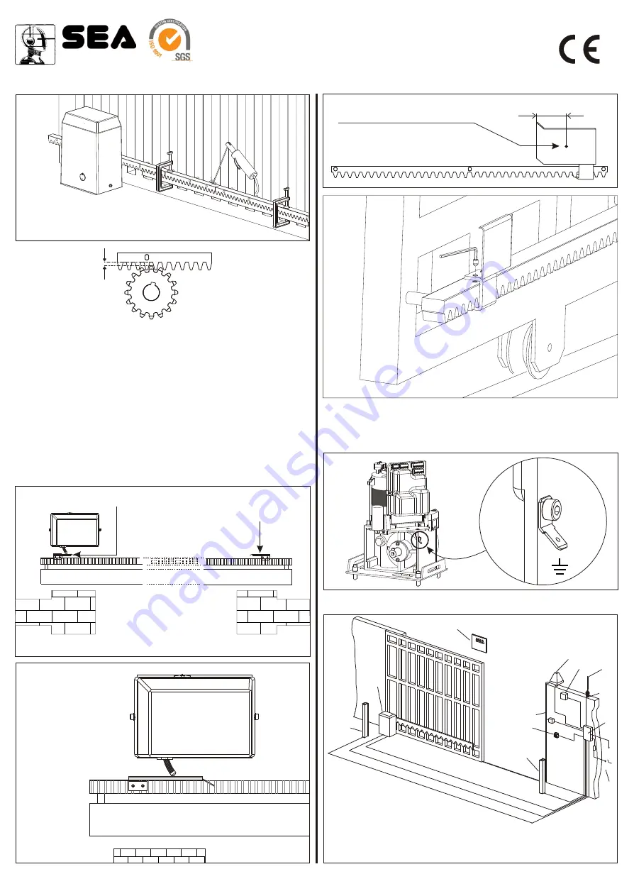
To set up and adjust the limit switches in opening, follow the instructions
written here (Fig. 12):
- Bring the gate in complete opening,
- Place the limit switch plate on the gear rack to have the limit switch (spring in
case of mechanical limit switch (Fig. 13)) in correspondence with the X point
which is 50 mm from the folded side of the plate (Fig. 14) and fix it with the
supplied screws (Fig. 15).
6.2.
To set up and adjust the limit switches in closing, follow the instructions
written here (Fig. 12):
- Bring the gate in complete closing,
- Place the limit switch plate on the gear rack to have the limit switch in
correspondence with the X point which is 50 mm from the folded side of the plate
(Fig. 14) and fix it with the supplied screws (Fig. 15).
Fig. 12
1,5 mm
Fig. 11
Closing limit switch
Opening limit switch
Fig. 13
Fig. 15
50 mm
X
Fig. 14
Place where the spring (mechanical
limit switch)
Through the braking trimmer adjustment placed on the electronic control unit it is
possible to stop the gate in the point desidered.
7. GROUNDING (Fig. 16)
8.
(Fig. 17)
CABLE LAYOUT
2x
5
1,
2x ,5
1
3x1,5
1x1,5
1 5
2x ,
1
3x ,5
1,5
2x
x1
3
,5
6 1,5
x
x
8 1,5
1xRG58
1
2
3
4
11
5
6
7
8
9
10
Fig. 17
REV 01 - 03/2005
1) TORG operator
2) Left photocell
3) Right photocell
4) Pneumatic safety edge
5) Key switch
6) Flashing warning lamp
7) Radio receiver
8) Antenna
9) Warning notice
10)Electronic control unit
11) 16A- 30mA differential switch
Fig. 16


