Sistemi elettronici
di Aperture Porte e Cancelli
9. RISK EXAMINATION
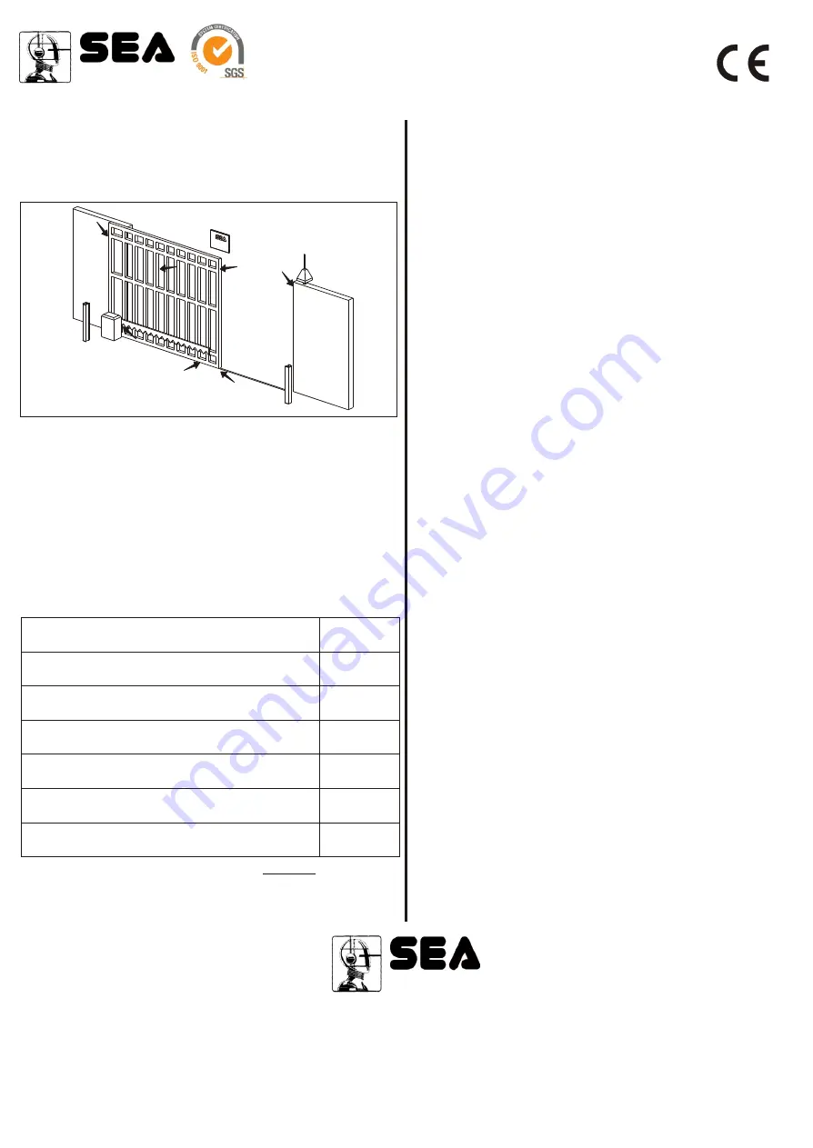
The points pointed by arrows in Fig. 18 are potentially dangerous. The installer
must take a thorough risk examination to prevent crushing, conveying, cutting,
grappling, trapping so as to guarantee a safe installation for people, things and
animals (
)
Re. Laws in force in the country where the installation has been made.
NOTICE
SEA s.r.l can not be deemed responsible for any damage or accident caused by
product breaking, being damages or accidents due to a failure to comply with the
instructions herein. The guarantee will be void and the manufacturer
responsibility (according to Machine Law) will be nullified if SEA Srl original spare
parts are not being used.
This is a quotation
from the GENERAL DIRECTIONS that the installer must read carefully before
installing. Packaging materials such as plastic bags, foam polystyrene, nails etc
must be kept out of children’s reach as dangers may arise.
The electrical installation shall be carried out by a professional technician who
will release documentation as requested by the laws in force.
Fig. 18
PERIODICAL MAINTENANCE
Check the release function
Verify the functioning of the electronic clutch
Check the distance between the pinion and the rack
(1.5 mm)
Check the wear condition of the pinion and of the rack
Check the fixing screws
Check the integrity of the connection cables
Check the function and the limit switch condition in opening
and closing and the related plates
Annual
Annual
Annual
Annual
Annual
Annual
Annual
All the above described operations must be made exclusively by an authorized
installer.
Sistemi elettronici
di Aperture Porte e Cancelli
SEA S.r.l.
Zona industriale 64020 S.ATTO Teramo - (ITALY)
Tel. 0861 588341 r.a. Fax 0861 588344
www.seateam.com
seacom@seateam.com
DECLARATION OF CONFORMITY
SEA declares under its responsibility that the product
Torg
meet the essential requisites provided for by the following European Directive
and following changes:
89/392/CEE (Machine Directive)
89/336/CEE (Electromagnetic Compatibility Directive)
73/23/CEE (Low Tension Directive)
SAFETY PRECAUTIONS:
All electrical work should conform to current regulations. A 16 A 0,030 A
differential switch must be incorporated into the source of the operators main
electrical supply and the entire system properly earth bonded. Always run mains
carrying cables in separate ducts to low voltage control cables to prevent mains
interference.
INTENDED USE:
The Torg operator has been designed to be solely used for the automation of
sliding gates.
SPARE PARTS:
To obtain spare parts contact:
SEA s.r.l. -Zona Ind.le, 64020 S. ATTO Teramo Italia
SAFETY AND ENVIRONMENTAL COMPATIBILITY:
Don’t waste product packing materials and/or circuits.
When being transported this product must be properly packaged and handled
with care.
MAINTENANCE AND OUT OF SERVICE:
The decommission and maintenance of this unit must only be carried out by
specialised and authorised personnel.
NOTE: THE MANUFACTURER CAN NOT BE DEEMED RESPONSIBLE FOR
ANY DAMAGE OR INJURY CAUSED BY IMPROPER USE OF THIS
PRODUCT.
SEA
reserves the right to do changes or variations that may be necessary to its
products with no obligation to notice.
IMPORTANT:
SEA advises the installation of Encoder system for higher anti-crushing
security where not foreseen.
REV 01 - 03/2005


