background image

NOTES


The electrical installation and the operation logics must comply with current regulations. Keep the power cables (motors, power 
supply) separated from the control cables (push-buttons, photo-eyes, radio, etc.). Separate conduits should be used to prevent 
noise issues. 

Note:


Use “cable clips” and/or “duct/box pipes” fitting close to the control panel box so to protect the interconnection cables 

against pulling efforts.

Note:

   The beam is not equipped with movement inversion system in case of obstacles. To respect the laws EN 12453 and   EN 

12445 it is recommended to insert external disposals into it.

INTENDED USE


VELA system has been designed exclusively for the automation of barriers. 

SPARE PARTS

The spare parts orders must be sent to:
     

 SEA s.r.l.  Zona Ind.le, 64020 S.ATTO  Teramo  Italy

SAFETY AND RESPECT FOR THE ENVIRONMENT


We recommend not to spoil the environment with product and circuit packing material. 

CONFORMITY REQUIREMENTS

VELA automation system complies with the following standards: 

 (Machine Directive)

 (Electromagnetic Compatibility Directive)

 (Low Voltage Directive)

2006/42/CE
2004/108/CE
2006/95/CE

English

Sistemi Elettronici

di Apertura Porte e Cancelli

International registered trademark n. 804888

®

To the attention of users and technicians 
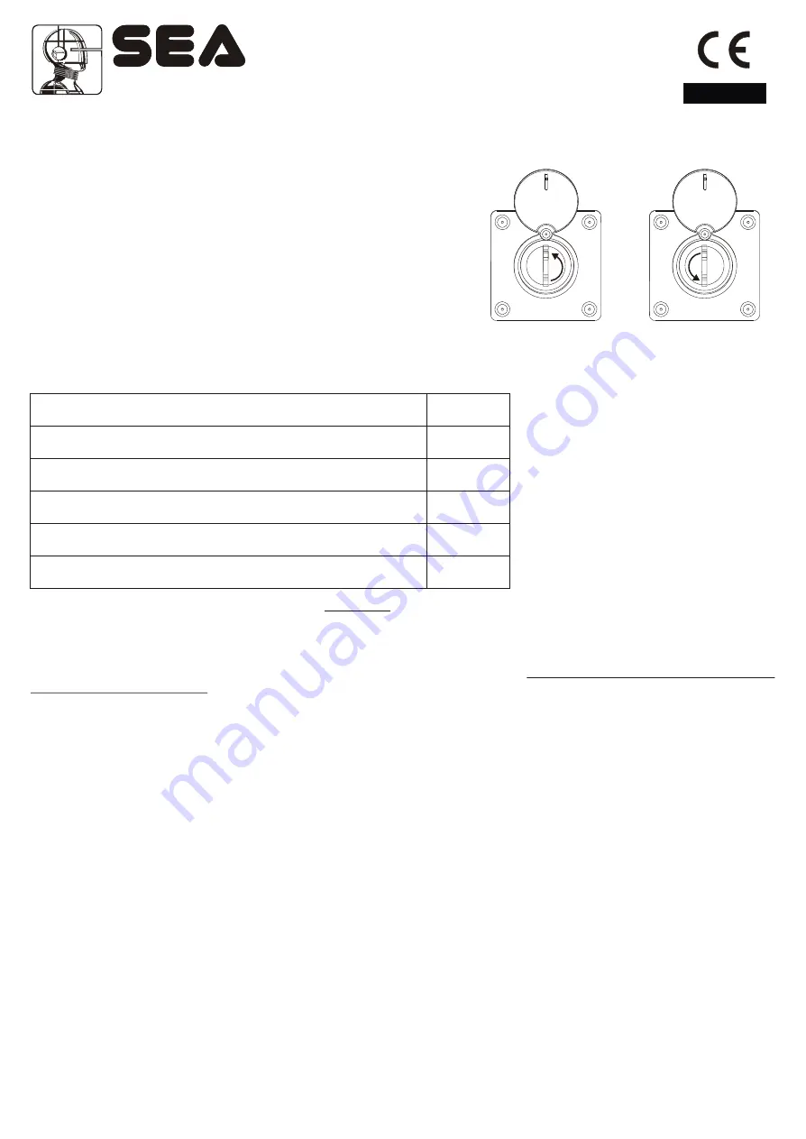
 12) Release system

To release operate as follwos 

-       Turn the protection cap of the lock.
-     Insert the key into the same and turn it about 180° into anti-clockwise         

direction until the beam is released (Fig. 18).

-       Open manually the beam.

        
To re-lock operate as follows

-       Turn the key into clockwise direction until it’s blocked. (Fig. 19).
-       Extract the key in vertical position.
-       Re-close the protection cap.

Fig.18

Fig.19

180°

PERIODICAL MAINTENANCE

Check the functionality of the release

Lubricate the bearing of the balance

Check the efficiency of the spring

Check the beam fixing screws and the balance and the casing

Check the integrity of the connexion cables  

Check and eventually adjust the efficiency of the By pass valves

Annually

Annually

Annually

Annually

Annually

Annually

All above mentioned operations must be executed exclusively by authorized installers.

INITIAL CHECK AND PUTTING IN SERVICE 

After having completed all necessary operations, for the correct installation of the product VELA, described in the present manual 
and after having valued all resting risks which could arise in whatever installation 

is necessary to test the automation to 

guarantee the max. security 

and in particular way to guarantee the respect of what foreseen by the law and the normatives in 

force. In particular the test must be executed following the   

EN12445

 ruel which establishes the testing methods for the testing of 

the gate operators respecting the established limits by the 

EN 12453 law. 

Cod. 67410035                                                        Rev 06 - 06/2010                                                              

25

Summary of Contents for VELA

Page 1: ...rol of the present inertial force in case of lack of power supply and a release system allows the manual opening in case of emergency The automation system is composed of the following elements 1 Adjustable mechanical stop 2 Manual release with DIN key 3 Galvanised steel rocker arm 4 VELA casing cover with lock and DIN key 5 Balancing spring 6 Electronic control unit GATE 1 code 23001120 1 a compl...

Page 2: ... cod 23001120 1 Technical features Overall dimensions 85 B am rotation axis 0 e Round beam profile Rectangular beam profile English INSTALLATION INSTRUCTIONS 1 Spring position Thanks to its high flexibility the barrier you are installing can be closed on the right hand or left hand side of the post according to your needs e g if the spring is on the right hand side the guard closes on the left see...

Page 3: ...g m i Conduit 500 0 30 2 Foundation plate anchoring Make a 500 x 500 x 300 mm depth hole in the ground Widen the foundation plate clamps till they reach approx 60 Fig 3 Fill the hole with R425 concrete and place the foundation plate as shown in Fig 3 Accurately level the plate The middle hole of the plate must be used for cable routing Therefore make sure that the conduit connected to the hole com...

Page 4: ...010 3 7 mm 11902020 3 5 8 mm 11902005 3 5 8 mm 11902015 Opening times Pump Opening time 1 7 5 s 1 5 5 0 s 2 3 5 s 2 speed 2 5 s 4 Fixing of the spring on the rocker arm Insert with care the roller bearing C in the buckle B and execute the assemblage as Fig 5 Lubricate with grease the bearing and the washers Mount the resting devices as shown in Fig 5 At the end of installation take off the breathe...

Page 5: ... meters Insert the bracket of beam anchorage in vertical position and fix it with the special screw and washer Insert the beam on the bracket and fix it with the special screws the washers and the nuts Fig 7 Attention Before inserting the bracket of anchorage insert the screws of anchorage into the same Tightening screw and washer Beam anchoring bracket Round beam Grooved shaft beam anchoring brac...

Page 6: ...Note For 4 and 5 m beams it is recommended to use the fork support or the flexible support Sistemi Elettronici di Apertura Porte e Cancelli International registered trademark n 804888 English Fig 9 Cod 67410035 Rev 06 06 2010 20 ...

Page 7: ...7 Mounting of the skirt on the beam Fig 10 Fig 11 English Sistemi Elettronici di Apertura Porte e Cancelli International registered trademark n 804888 Cod 67410035 Rev 06 06 2010 21 ...

Page 8: ...Sistemi Elettronici di Apertura Porte e Cancelli International registered trademark n 804888 Fig 12 Fig 13 English Mounting of the skirt on the oval beam Cod 67410035 Rev 06 06 2010 22 ...

Page 9: ...g obtained the balancing lock the nuts of the spring stretcher with the counter nut and re block the motor Spring nut stretching Anchoring lock nut 10 Beam levelling Note this operation must be carried out only if the beam is not perfectly horizontal closing stage or vertical opening stage at the end of its stroke Release the beam with the special manual release so that it is free to open and clos...

Page 10: ... 4 Key switch Key Plus 5 Radio receiver 6 Flashing light Flash 7 Push button station 8 Differential switch Sistemi Elettronici di Apertura Porte e Cancelli International registered trademark n 804888 1 1 2 2 4 4 5 5 6 6 7 7 8 8 2x1 2x1 2x1 4x1 3x1 5 3x1 Fig 17 3 3 3x1 GHOST 40 GHOST 50 ACCESSORIES FOR VELA FORK SUPPORT FEXLIBLE SUPPORT ONLY BEAM it is reccommended to mount with beams which are lon...

Page 11: ...lease operate as follwos Turn the protection cap of the lock Insert the key into the same and turn it about 180 into anti clockwise direction until the beam is released Fig 18 Open manually the beam To re lock operate as follows Turn the key into clockwise direction until it s blocked Fig 19 Extract the key in vertical position Re close the protection cap Fig 18 Fig 19 180 PERIODICALMAINTENANCE Ch...

Page 12: ...ortant to follow with attention all the advises and instructions in this manual Awrong installation or a wrong use of the product can cause sever damages to people 2 The max length of the power supply cable between control unit and motors is 10m use cables with 2 5 mm section Use wirings with double insulated cables cables with sheath up to the immediate proximities of the terminals especially for...

Page 13: ...ention on the installation Disconnect also possible battery buffers if present Make sure that the earth installation has been correctly made connect all the metallic parts of the closing doors gates etc and all the components of the installation provided with earth terminals Apply all the safety devices photocells sensitive edges etc which are necessary to protect the area from dangers of crushing...

Reviews: