background image

10)


Electrical system

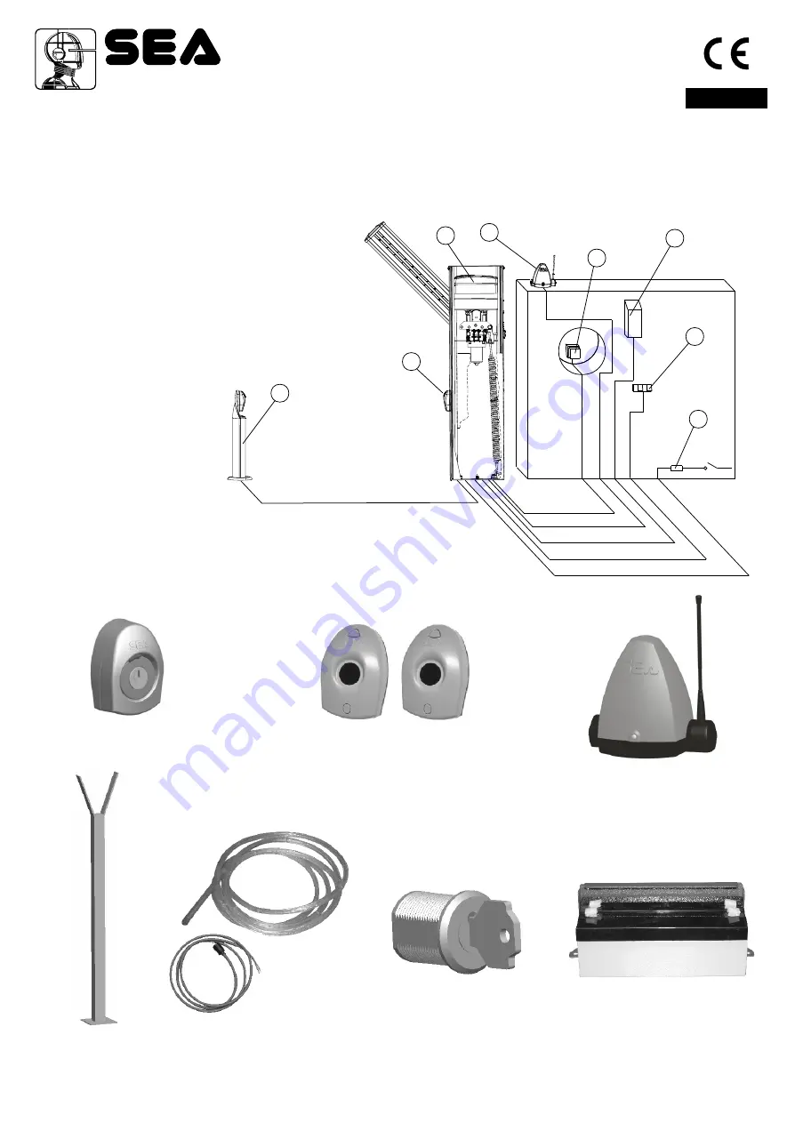
Fig. 11 sketches the electrical system that the barrier requires. 
The two numbers located near the electrical cables indicate the cable number and section.

Captions:

1- VERG electronic control unit
2- Transmitting photocell
3- Receiving photocell
4- Key switch
5- Radio receiver
6- Flashing light
7- Push-button station
8- Differential switch

English

Sistemi Elettronici

di Apertura Porte e Cancelli

International registered trademark n. 804888

®

ACCESSORIES 

FOR 

VERG

FORK SUPPORT

BATTERY KIT 

PHOTOCELLS

KEY SWITCH  

WARNING LAMP

Fig.11

1

1

2

2

3

3

4

4

5

5

6

6

7

7

8

8

2x1

2x1

4x1

3x1,5

3x1

Fig.11

2X1   1xRG58

18

Cod. 67411465                                                 Rev.00 - 12/2012                                                              

RELEASE LOCK

(Optional)

LED 

LIGHTS KIT

Summary of Contents for VERG 24V

Page 1: ... system is composed of the following elements 1 Adjustable mechanical stop 2 Manual release with key 3 Galvanised steel rocker arm 4 VERG 24V casing cover with lock and DIN key 5 Balancing spring 6 Electronic control unit 7 Foundation plate out of galvanized steel 8 Emergency batteries 2x12V 2Ah 9 24V 2400 rpm electric motor 10 Reduction gear 11 Cataphoresis treated and polyester painted VERG 24V ...

Page 2: ...Fig 2 Fig 1 Opening on the right Opening on the left 12 230 V 5 50 60 Hz 115 V 5 50 60 Hz 24Vdc 60 W 2400 20 55 C IP55 Yes 60 A Yes E 39 kg USER 1 24V RPM Adjustable mmeter lectronic Cataphoresis treated and polyester painted 128 56 1148 288 203 VERG 230V VERG 115V Note The frequency of use is valid only for the first hour at 20 C room temperature OVERALL DIMENSIONS To guarantee longer life of the...

Page 3: ...ng nuts and washers Hole for the conduit containing the electrical cables 3 Post anchoring on the foundation plate Place the casing so that the holes on the base match the screws located on the foundation plate Make sure that the conduit for the cables goes through the large hole of the casing base Insert the bracket for anchoring the spring A in case of left hand mounting B in case of right hand ...

Page 4: ...ing of the spring Anchor the spring on the bracket which has been mounted before S Insert the rod of the spring into the bracket B and insert the nuts D without tightening them OVAL BEAM Length m 3 4 5 Balance position 1 4 1 4 1 4 Spring Ø mm 6 7 5 8 5 Note Strictly follow the opening time to avoid bad working Note The springs and the bracket of anchorage are supplied with the beam Opening time 3 ...

Page 5: ... Note For 4 and 5 m beams it is recommended to use the fork support or the flexible support English Sistemi Elettronici di Apertura Porte e Cancelli International registered trademark n 804888 Fig 7 15 Cod 67411465 Rev 00 12 2012 ...

Page 6: ... 8 Beam levelling Note this operation must be carried out only if the beam is not perfectly horizontal closing stage or vertical opening stage at the end of its stroke Release the beam with the special manual release so that it is free to open and close manually Release the screws of the limit switch on unscrewing the nuts on the mechanical stops fig 9 Loosen or tighten the stop screws so that the...

Page 7: ... mA Battery Ah 9 Battery charger circuit English Sistemi Elettronici di Apertura Porte e Cancelli International registered trademark n 804888 GND GND GND GND PSOL PSOL BAT BAT 28V 28V S S USER24 charge 200mA Solar Panel Batteries GND GND Grey connector CN1 charge 360mA charge 800mA 12V 12V 12V 12V 12 or 16 7 2 800 360 200 Fig 10 17 Cod 67411465 Rev 00 12 2012 ...

Page 8: ...3 Receiving photocell 4 Key switch 5 Radio receiver 6 Flashing light 7 Push button station 8 Differential switch English Sistemi Elettronici di Apertura Porte e Cancelli International registered trademark n 804888 ACCESSORIES FOR VERG FORK SUPPORT BATTERY KIT PHOTOCELLS KEY SWITCH WARNING LAMP Fig 11 1 1 2 2 3 3 4 4 5 5 6 6 7 7 8 8 2x1 2x1 4x1 3x1 5 3x1 Fig 11 2X1 1xRG58 18 Cod 67411465 Rev 00 12 ...

Page 9: ...OT SHOULDER ANY RESPONSIBILITIES IN CASE OF DAMAGE CAUSED BY INAPPROPRIATE WRONG OR CARELESS USE SEAreserves the right to make all the necessary changes and modifications of the products and or manuals without giving prior notice English Sistemi Elettronici di Apertura Porte e Cancelli International registered trademark n 804888 11 Release system To release operate as follows Turn the protection c...

Reviews:

Related manuals for VERG 24V