


E-15
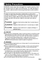
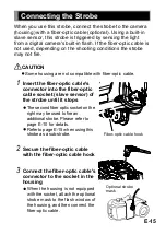
Connecting the Strobe
CAUTION
1
3
Some housing are not compatible with fiber-optic cable.
When you use this strobe, connect the strobe to the camera
(housing) with a fiber-optic cable (optional). Using a built-in
slave sensor, this strobe is triggered by sensing the light
from a digital camera's built-in flash. If the fiber-optic cable is
not used, depending on the shooting conditions the strobe
may not fire.
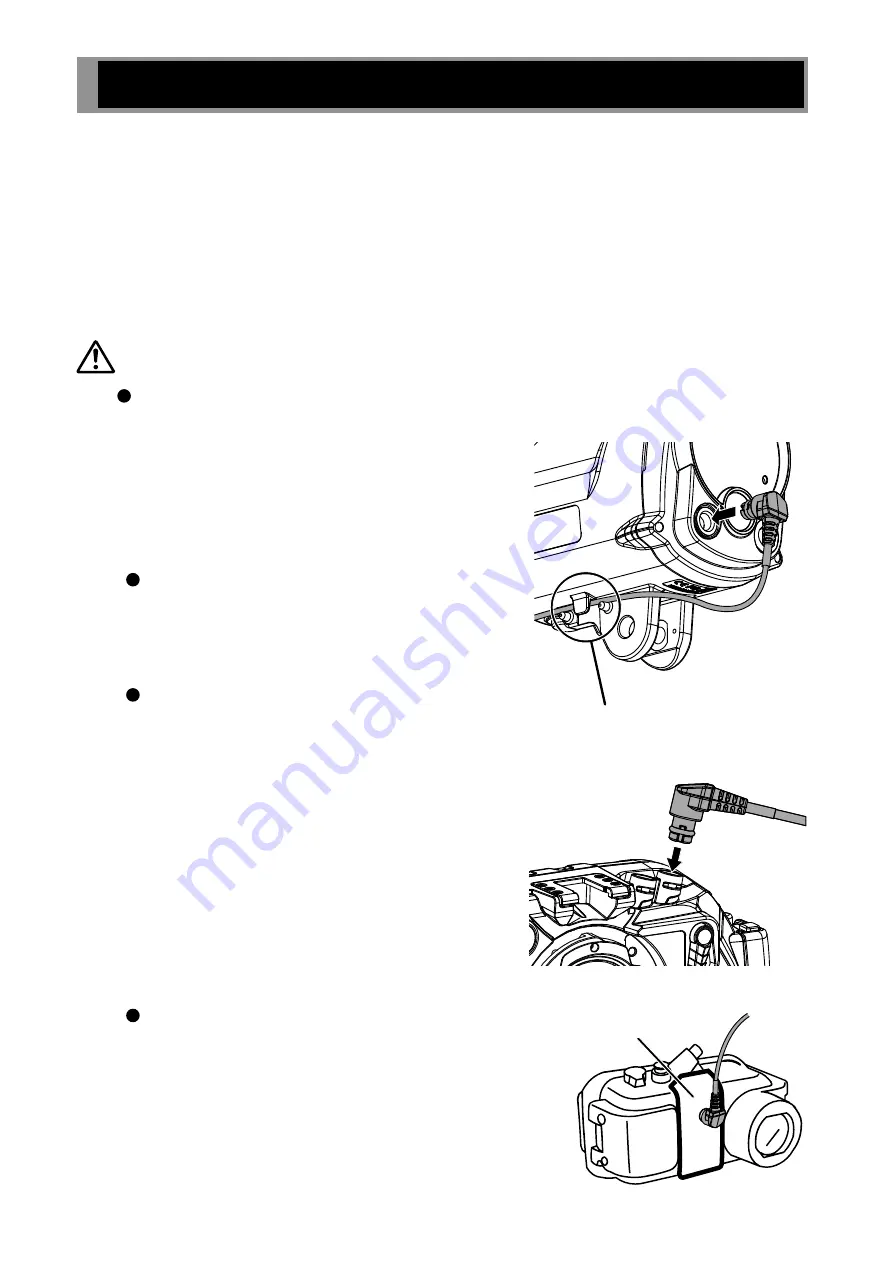
Insert the fiber-optic cable's
connector into the fiber-optic
cable socket (slave sensor) of
the strobe until it stops
Connect the fiber-optic cable's
connector to the socket in the
housing
2
Secure the fiber-optic cable
with the fiber-optic cable hook
When the housing is not equipped
with the socket, attach the optional
strobe mask to the flash window of
the housing, and then connect the
fiber-optic cable.
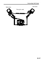
The second fiber optic socket on the
right may be used to fire an
additional strobe. Please refer to
page E-10 for details.
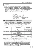
Refer to page E-15 when using this
strobe as a sub-strobe.
Optional strobe
mask
Fiber-optic cable hook