background image

 SC4x0 Technical manual 


      Page 4 of 34 

SeaCom 


   Rev 

2.00 

7.2


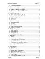
Voice control considerations ..................................................................................... 17


8.


Electrical layout ............................................................................................................. 18


8.1


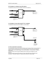
Example of a simple set up with headset ................................................................. 18


8.2


Example of a simple set up with handset ................................................................. 19


8.3


Example of set up with remote PTT for loudhailer .................................................... 19


8.4


Ground & shield connections .................................................................................... 19


9.


Mounting & programming .............................................................................................. 20


9.1


Power supply & grounding considerations ................................................................ 20


9.2


Programming the type of headset & VOX ................................................................. 20


9.3


Adjusting microphone gain ....................................................................................... 20


9.4


Relay function ........................................................................................................... 21


9.5


Dial signal type ......................................................................................................... 21


9.6


Hands free voice control ........................................................................................... 21


9.7


Bell signal and volume .............................................................................................. 21


9.8


PA volume ................................................................................................................ 21


9.9


External speaker ....................................................................................................... 22


9.10


Adjusting external dimmer input ............................................................................... 22


9.11


Local external microphone ........................................................................................ 22


10.


Parameter list ................................................................................................................ 23


10.1


Level 1 parameters ................................................................................................... 23


10.2


Level 2 parameters ................................................................................................... 23


10.3


Level 3 parameters ................................................................................................... 24


10.4


Parameter list for hidden menu ................................................................................. 25


11.


Serial monitor ................................................................................................................ 27


11.1


Function .................................................................................................................... 27


11.2


Commands ............................................................................................................... 27


11.3


Commands use full for workshop testing .................................................................. 27


11.3.1


Set Relay -command ......................................................................................... 28


11.3.2


To pass audio from microphone to speaker ...................................................... 28


11.4


Commands use full for development & testing ......................................................... 28


11.4.1


Memory monitor & manipulation ........................................................................ 28


11.4.2


Eeprom data ...................................................................................................... 28


11.4.3


Busy tone detector ............................................................................................. 28


12.


Simple faultfinding ......................................................................................................... 29


12.1


No ‘life sign’ .............................................................................................................. 29


12.2


Spontaneous reset .................................................................................................... 29


12.3


Unable to hang up in hands free mode ..................................................................... 29


12.4


Noisy or scratchy sound quality ................................................................................ 29


12.5


No direct in, no PA or no command call ................................................................... 29


12.6


Dialing problems ....................................................................................................... 29


12.7


Low or distorted sound from microphone ................................................................. 29


Summary of Contents for SC410

Page 1: ... end flush mount telephone for wheelhouse ECR SC420 a high end bulkhead mounted heavy duty telephone for E R etc Doc ID Revision history Date D Rev S Rev Init Comment 2008 05 28 01 00 080409 LAF Document created 2008 11 12 01 01 081106 LAF Document updated to new hands free funk 2009 10 07 02 00 091007 LAF Busy detect local external mode ...

Page 2: ...SC4x0 Technical manual Page 2 of 34 SeaCom Rev 2 00 Technical Manual SC410 SC420 P410 P420 ...

Page 3: ...12 4 1 Line voltage ringing voltage detector 12 4 2 16 kHz control signals 12 4 3 FSK CLIP data 12 5 Hidden menu 13 5 1 System info 13 5 1 1 Device software family 13 5 1 2 Serial number 13 5 1 3 Production date 13 5 1 4 System state 13 5 1 5 E bank 14 5 1 6 Error code 14 5 2 Monitor line 14 5 3 Monitor input 15 5 4 Set parameter xx 15 5 5 Recall factory 15 5 6 Erase eeprom 15 5 7 Reset 15 5 8 Sys...

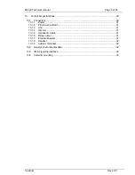
Page 4: ...sting external dimmer input 22 9 11 Local external microphone 22 10 Parameter list 23 10 1 Level 1 parameters 23 10 2 Level 2 parameters 23 10 3 Level 3 parameters 24 10 4 Parameter list for hidden menu 25 11 Serial monitor 27 11 1 Function 27 11 2 Commands 27 11 3 Commands use full for workshop testing 27 11 3 1 Set Relay command 28 11 3 2 To pass audio from microphone to speaker 28 11 4 Commands...

Page 5: ...tors 30 13 1 1 Power 31 13 1 2 PE protective Earth 31 13 1 3 Line 31 13 1 4 Dimmer 31 13 1 5 Handset cradle 31 13 1 6 Relay output 31 13 1 7 External speaker 31 13 1 8 Headset 32 13 1 9 Cable terminals 32 13 2 General environmental data 32 13 3 I O signaling interface 32 13 4 Cutout mounting 33 ...

Page 6: ...afe distance 7m Software ID 2007001 Software rev 091007 All produced units are marked with type id and serial number WARNING Do not disassemble the device as high voltage may present on the PCB or terminals Telephone line signal may contain voltage ranging from 48Vdc up to 130Vac peak Always switch off ALL power or disconnect ALL terminals before disassemble DO NOT REMOVE PROTECTIVE EARTH PE when ...

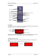
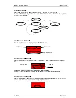
Page 7: ... and old data is restored 2 2 Display Power on info When the phone is in power on state it will show information about hardware and what software it is running 4 sec after power on display will enter idle state unless no line is detected After 4 sec Display Local Speaker Call indicator Speed dial Function keys Redial Pause R key Local PTT Light sensor Menu key Mem dial key Hands free Key Speaker k...

Page 8: ...n the window operation is reset When the menu system is active and no keys are pressed all operations will be canceled after 10 sec If data was being entered operation is canceled and old data restored If a call is received while operating the menu system immediate timeout is generated and the telephone will revert to idle to show incoming call or idle state A few special menus are excepted from t...

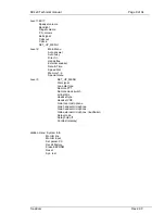
Page 9: ...nal speaker Date Time Speed dial Memory 1 6 Special menu Level 3 SET_UP_MENU Dial signal Loop dial type Remote PTT Remote Hook switch Lcl Ext Mic Headset type Headset VOX Gain local microphone Gain handset microphone Gain headset microphone Gain external microphone loudhailer Relay mode Relay hold off Contrast display Hidden menu System Info Monitor line Monitor input Set param XX Recall Factory E...

Page 10: ...i the phone is busy display will show the following info If mute state speaker or hands free changes status field is updated If change to another audio connection e g handset is made it will be shown in the display 3 2 3 Display Error mode When the telephone detects missing line it will enter error mode Here the cause of current error will be shown as flashing text or error code Currently only lin...

Page 11: ...system error has occurred 3 4 Light sensor backlight The light sensor in the front is used to control the backlight in the keyboard and display when backlight mode is set to automatic The raw data from the sensor can be read out via the hidden menu If two units are placed side by side and dimming is controlled externally dimmer input needs to be calibrated for the two units to have same intensity ...

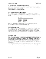
Page 12: ...l set by the processor From the hidden menu system it is possible to adjust trigger level for the detector Only I rare cases where noise is disturbing the detector adjustment of the 16 kHz threshold level is needed or if the detector needs to be disabled Setting the level to 0 or 100 will disable the detector 4 3 FSK CLIP data If the exchange is programmed to issue FSK data caller s ID can be disp...

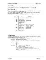
Page 13: ...n date System state E_Bank Error code 5 1 1 Device software family This item has partly been replaced by the power up menu but will show in plain text the basic type of device 5 1 2 Serial number This item is the device unique serial number If this number is missing error is indicated via the call indicator flashing and an entry is made to the internal error log 5 1 3 Production date This item sho...

Page 14: ... Set error state 0008 Temperature alarm set if board temp 80 C 0010 Temperature warning set if board temp 70 C Switch off all backlight Decrease speaker vol to step 7 44 0020 No serial number Set error state 0040 Watch dog error Set error state 0080 IRQ time too long 5 2 Monitor line This item will monitor all line events This menu will not exit idle when hook off or timeout It is possible to pres...

Page 15: ...s out of range data will be replaced by high or low boundary value Depending on the type of data Or can be entered using the F keys F3 will erase last entered digit 5 5 Recall factory This function will clear all user settings and restore them to factory values Use this function if there is any doubt re current settings to set all parameters From software 090928 all new parameters will automatical...

Page 16: ...arm log and error condition is indicated by the Call indicator If the temperature exceeds 85 C an alarm is given backlight supply is disconnected if the unit is active volume is lowered to step 7 if set higher for reducing the power dissipation When temperature of the power amplifier reaches approx 140 C it will shut down due to thermal protection 6 4 Program deadlock protection The processors int...

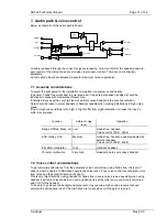
Page 17: ... saturation or cause the input to suffer for saturation Location Ambient noise level Operation Bridge Offices Mess etc Low Hands free handset Voice control 10dB 25dB ECR Galley SCC Medium Hands free handset possibly assisted by external speaker Voice control 30dB 40dB ER SGR Generator High Handset headset Thruster Hydraulics Very high Headset and in some cases handset 7 2 Voice control considerati...

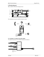
Page 18: ...Dimmer 0V Hook SW 0V Hook SW Power Amp DC DC 0V 5V Line Tip Ring PTT Speakers Mic Display Keypad Line 24V Dimmer optional 2 2 2 2 6 6 2 Headset Handset Ext speaker Loudhailer PE Headset SP Headset PTT Headset Mic SC410 420 24V 0V Relay COM Relay NO or NC PE T1A T2A PE NOTE If shield is connected at APBX do NOT connect to PE at telephone end Always only connect one end due to possibly high ground c...

Page 19: ...X do NOT connect to PE at telephone end Always only connect one end due to possibly high ground current when used off shore To bell or alarm relay coil NOTE If connected to DC coil use protection diode Hook Sw 0V Cradle switch must be potential free Switch must close when handset is off hook Cradle Switch is connected to Hook Sw on telephone If cradle have a double switch use the other for connect...

Page 20: ...full duplex mode when connected to another phone using hands free some voice control may be needed to maintain control of speech direction VOX will raise or lower gain towards the line for better speech detection at the hands free end This will enhance the speech quality by raising the gain when speaking into the headset microphone and lower it when not If voice switching is used at the hands free...

Page 21: ...disconnecting any local speaker for making PA calls to a system outside the exchange to avoid feedback through the telephone The relay function can be programmed as inverse function is power fail indication is needed 9 5 Dial signal type Normally DTMF signals are use to dial numbers However if connected to older systems or special adoption is needed the telephone can be programmed to use pulse dia...

Page 22: ...volt Go to the hidden menu and read out the dimmer input value Note it for later use Set the dimmer to max output and read out the dimmer input value from the hidden menu Use the following formula to calculate offset and gain factor AOffset Dimmer input value in at 5 volt AGain 100 Dimmer input value in at max Dimmer input value in at 5 volt The values for AOffset AGain can be entered via set para...

Page 23: ...equal to 3dB PA volume 0 100 in 16 steps Factory setting 37 69 or step 11 Each step is equal to 3dB Bell signal Tone 1 Tone 8 Factory setting Tone 1 10 2 Level 2 parameters Parameter Range Auto answer 0 50 0 disabled Factory setting 0 Auto busy On Off Factory setting Off Direct in On Off Factory setting On Hands free Disabled 10dB 40dB in steps of 5dB External speaker On Off Factory setting Off Da...

Page 24: ...mode using local speaker and headset mic Headset type Electret condenser or dynamic Factory setting dynamic Refers to the type of microphone used with the headset Headset VOX On or Off Factory setting Off See user manual Gain local Mic 0 100 in 16 steps Factory setting 64 Each step represents 2 7dB increase Step 9 to step 10 will change HW gain Gain handset Mic 0 100 in 16 steps Factory setting 36...

Page 25: ...ll range value 100 equals x1 00 200 equals x2 00 07 Backlight ABS max 0 100 Factory setting 100 Used to limit backlight intensity Sets max endpoint of total span 08 Backlight ABS min 0 100 Factory setting 0 Used to prevent backlight from going total off Sets min endpoint of total span 09 Max PA volume 0 17 Each step equals 3dB Factory setting step 10 Sets the volume used if PA call using volume ov...

Page 26: ...535 Used for SW development 15 Global Var2 0 65535 Used for SW development 16 Speaker relay delay 0 2 2 0 Cut in delay for ext speaker 17 Busy gain level 50 200 Signal level to busy detector 18 Busy detection maskl 0x0000 0xFFFF Factory is 0x0006 Mask set tone pattern enab ...

Page 27: ...d line codec pass will engage the codec and pass audio from mic to line from line to speaker mirror on mirror off will twist output channels on the codec on off used pass audio from mic to speaker sgts xx will set gain to speaker to the step xx in gain table 0 20 sgtl xx will set gain to line to the step xx in gain table 0 20 gsin will display current system info software info error info re boot s...

Page 28: ...ect speaker or mic 11 4 Commands use full for development testing These commands should only be used by system developers as they may potentially cause the software to malfunction and reset In general only commands changing the contents of the eeprom cannot be recovered from a reset Meaning at reboot will reset all data to initial values except data in eeprom if changed 11 4 1 Memory monitor manip...

Page 29: ...round leaks 12 3 Unable to hang up in hands free mode If fitted with a handset or if hook switch input is shorted it is not possible to end current session conversation until handset is relocated in the cradle or input is open when conversation is carried out in hands free mode If no handset is connected remove any wires connected to hook switch input and recycle power If input is used for remote ...

Page 30: ... may be orientated with the cables 180 or 90 angled However 180 deg is the only option for the 420 type NOTE If connected as 180deg and relocated as 90deg all connections are mirrored posing a great risk of damaging the unit Important DO NOT remove dispose the ventilation gland Applicable for the SC420 only Only connect power to power relay switch inputs never apply power on any other terminals Al...

Page 31: ...e switch for hook signaling must be a potential free switch capable of switching 30Vdc and must be in off state when handset is positioned in the cradle Depending on the type of hardware switch may be located either in the handset or in the cradle The speaker output is short circuit protected by a 47ohm serial resistor The max output current is approx 20mA equivalent to 3mW in 8 ohm or 13mW in 32o...

Page 32: ... 24Vdc 1 5Adc Ambient temperature operation 25 70 C Ambient temperature storage 30 70 C Humidity vibration EMC ESD IEC60945 Compass safe distance 7 meters Surface Water and oil resistant Environmental RoHS compliant 13 3 I O signaling interface Supply 24Vdc 30 25 1 5Adc Dimmer input 0 30 5 24V 0 100 20mA Line voltage idle 20 50Vdc Line voltage ringing 40 90Vrms 20 50Hz Pure AC and AC mixed on DC L...

Page 33: ...SC4x0 Technical manual Page 33 of 34 SeaCom Rev 2 00 13 4 Cutout mounting NOTE compass safe distance is 7 meters ...

Page 34: ...SC4x0 Technical manual Page 34 of 34 SeaCom Rev 2 00 ...

Reviews: