Section 01
ELECTRICAL SYSTEM
Sub-Section 01
(INSTRUMENTS AND ACCESSORIES)
01-01-2
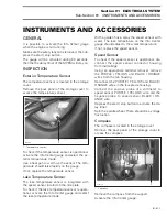
Change the direction of the compass. There
should be a change of direction on the Info Center
Gauge.
NOTE :
To check the accuracy of the com-
pass, you can use a portable compass and
point it in the same direction. Compare the given
directions, they should be the same.
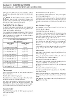
Fuel Baffle Pick-Up Sensor
To verify fuel sensor, a resistance test should be
performed with an ohmmeter allowing the float to
move up through a sequence.
The resistance measured between PINK / BLACK
and PINK wires must be in accordance with fuel
level (measured from under the flange) as speci-
fied in the following chart.
Tachometer
The PURPLE wire is the 12 VDC power source of
the tachometer.
The BLACK wire is the ground.
The GRAY wire is the pulse signal from the multi-
purpose electronic module (MPEM).
The TAN / BLUE wire is the signal for the red
warning LED. When the engine overheats, the
temperature sensor is grounded to the engine,
which closes the circuit and the LED turns on.
Speedometer
The PURPLE wire is the 12 VDC power source of
the speedometer.
The BLACK wire is the ground.
The PURPLE / YELLOW wire is the pulse signal
from the speed sensor.
The BLUE wire is the signal for the red warning
LED. When the oil level is low in the reservoir, the
oil sensor resistance is infinite and the light turns
on.
Info Center Gauge
The PURPLE wire is the 12 VDC power source of
the Info Center gauge.
The BLACK wire is the ground.
The RED / PURPLE wire is the 12 VDC from the
battery protected by a 5 A fuse on the MPEM. If
this wire is disconnected or if the fuse is blown,
the Infor Center gauge will not turn on.
The PINK wire is the signal for the red warning
LED. When the fuel level is low in the reservoir,
the fuel sensor resistance is high and the light
turns on.
The accuracy of some features of the Info Center
gauge can be checked with a potentiometer.
FUEL LEVEL
Disconnect the 4-circuit connector housing of the
Info Center gauge.
Using an appropriate terminal remover, remove
the PINK wire from the tab housing.
Reconnect the connector housing.
Disconnect the 2-circuit connector housing which
contains a PURPLE and BLACK wires.
Remove the BLACK wire from the receptacle
housing.
Reconnect the connector housing.
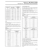
Connect potentiometer test probes to the PINK
and BLACK wires.
Adjust potentiometer to the resistance values as
per following chart to test the accuracy of the
gauge.
NOTE :
The gauge must be activated to ob-
tain a reading.
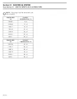
FUEL LEVEL AND RESISTANCE
(GSX and GTX)
FUEL LEVEL
(mm)
RESISTANCE
(
Ω
)
From 248.9 ± 5 and more
0 + 2.2
From 234.4 @ 248.8 ± 5t
17.8 ± 2.2
From 200.9 @ 234.3 ± 5
27.8 ± 2.2
From 167.4 @ 200.8 ± 5
37.8 ± 2.2
From 134.0 @ 167.3 ± 5
47.8 ± 2.2
From 100.5 @ 133.9 ± 5
57.8 ± 2.2
From 67.0 @ 100.4 ± 5
67.8 ± 2.2
From 40.1 @ 66.9 ± 5
77.8 ± 2.2
From 0 @ 40.0 ± 5
89.8 ± 2.2
'
'


