Enclosure core product
17
Enclosure rear panel
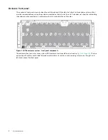
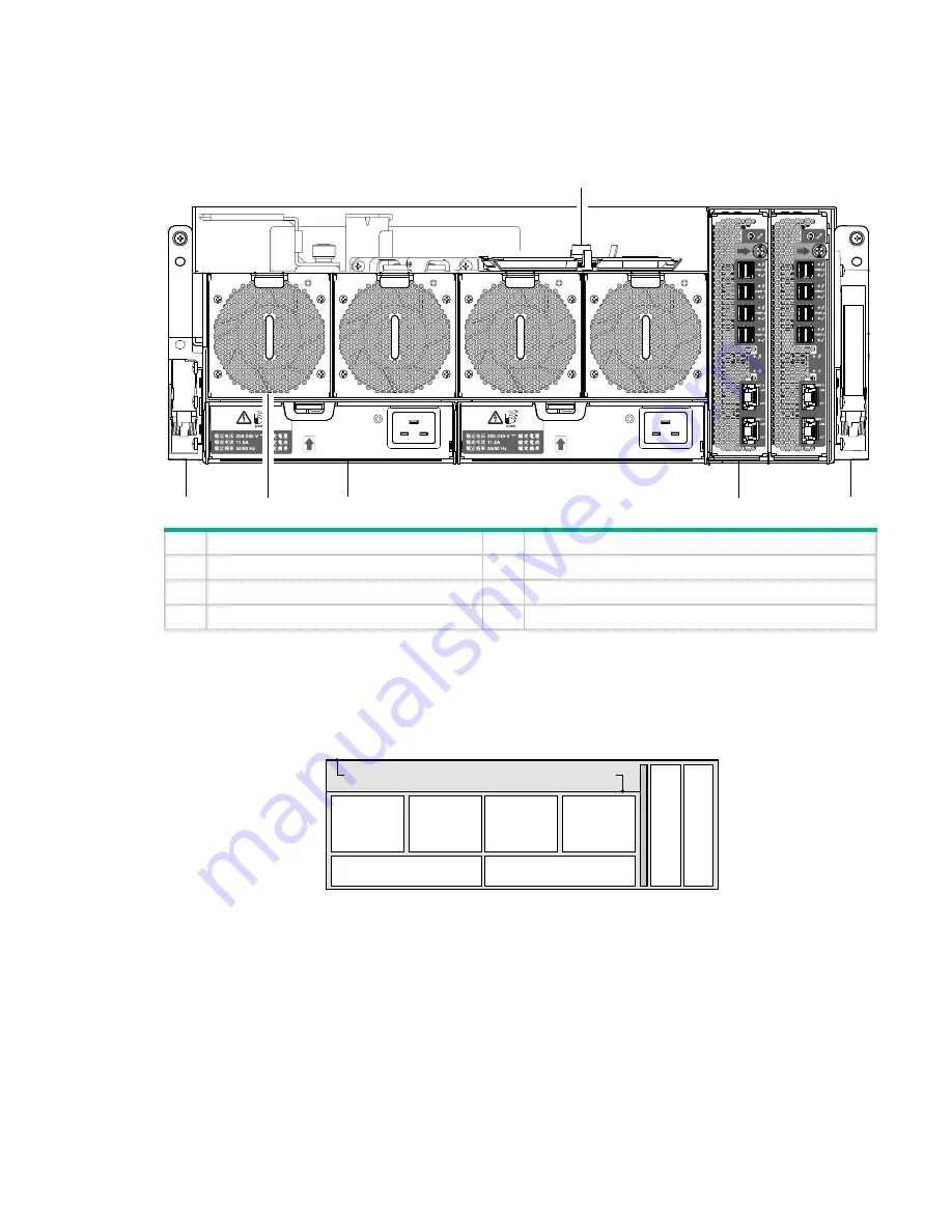
This enclosure rear panel view intentionally omits the optional lift handles that attach to the enclosure sides and that
must be removed before pushing the enclosure mounted on the rails into the rack. It also does not show the rails holding
the enclosure when mounted in a rack because the rails are behind the pull handles.
Figure 3 4U106 enclosure system – rear panel components
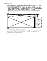
See
for a conceptual diagram showing the numbering for each module bay that can be accessed from
the rear panel.
Rear panel components
Figure 4 4U106 enclosure – rear panel module slot index diagram
3
1
6
5
2
4
No.
Description
No.
Description
1
Right ear assembly (as viewed from back)
4
Cable shelf and CMA bracket for coiled cables
2
System fan module (quantity–4)
5
IOM (quantity–2)
3
Power supply unit (quantity–2)
6
Left ear assembly (as viewed from back)
System
Fan Module
Slot 0
Slot 1
Slot 2
Slot 3
PSU
Module Slot 0
PSU
Module Slot 1
Controller Slot 0
Controller Slot 1
System
Fan Module
System
Fan Module
System
Fan Module
Cable management recess and cable shelf
IO
M
IO
M

