20
System overview
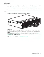
Enclosure top panel
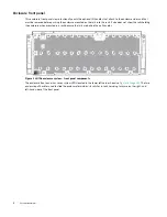
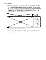
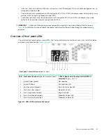
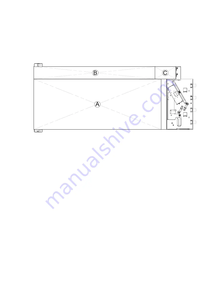
The enclosure top panel has two covers that can be removed for access to the internal components. The illustration
shows three parts of the top panel labeled as A, B, and C. See
for more details.
•
A: The main bay cover provides access to the hot-swap expanders and 96 drive slots. Panel A is divided into two
parts - front and rear. Both these parts are interconnected through a central hinge. It is not recommended to remove
entire main bay cover. At a time, you can access either front half or rear half of the main bay.
•
B: The removable auxiliary bay cover that provides access to 10 drive slots and the two internal fan modules.
•
C: A fixed part of the enclosure chassis that cannot be removed.
Figure 8 4U106 enclosure – top panel with covers installed
shows a top view of the enclosure with simplified covers. The illustration is oriented such that the
front of the enclosure is on left, and the rear of the enclosure is on the right. The rail kit and most of the cable
management arm geometry are omitted for clarity.

