24
System overview
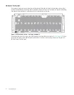
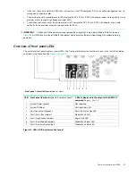
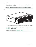
provides a conceptual diagram of module slot-index numbering as viewed from the top of a 4U106 enclosure
with all covers removed. To view the arrangement of PSU module slots—beneath the system fan slots—see
Figure 13 4U106 enclosure – top panel module slot index diagram
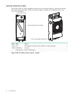
The 4U106 is designed for use with a full load of drives; however, it may also be partially populated.
WARNING!
If you partially populate the storage enclosure with disk drives, you must populate from front to back, filling
an entire lateral bay before populating the next bay.
Enclosure chassis
The 4U106 chassis consists of a sheet metal enclosure with integrated PCBAs. The enclosure is divided into a main bay
and an auxiliary bay. Each bay has a removable cover to provide access to plug-in modules known as field-replaceable
units (FRUs). The metal surfaces are free from non-conductive coatings and paint
•
The chassis has a 1.2 m rack mounting that enables it to be installed onto standard 1.2 m racks, and uses four EIA
units of rack space (7") for a 4U enclosure. Optional lift handles on the chassis side walls facilitate hoisting and
installation. See also
•
The cable management arm (CMA) routes cables from the controller channel and external connections and secures
them for in-rack servicing of the installed enclosure.
•
The drive channel bus-bar distributes power from the power midplane to 24 HDD baseplanes.
•
The four 24 HDD baseplane PCBAs support 96 drive connections in the drive channel.
•
The 10 HDD baseplane PCBs supports 10 drive connections in the controller channel.
•
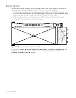
The enclosure top panel provides access to 106 low profile 3.5" LFF or 2.5" SFF (with adapter) drives, held vertically. Out of
these 106 drives, 96 drives are present below cover A (main bay cover), and 10 drives (and two controller channel fans) are
present below the cover B (auxiliary bay). See
for more details. Each drive slot holds a plug-in drive
carrier module. The top panel also provides access to the HS expander and controller fan FRUs.
•
Each 24 HDD base plane has a pair of hot-swappable expander cards (eight individual hot-swappable expander
cards). Each expander card plugs into a riser card that in turn connects to a baseplane.
•
Within the auxiliary bay, fans provide additional cooling for IOMs.


