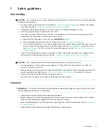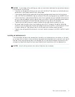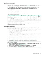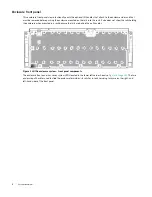
Overview of front panel LEDs
25
•
In the rear, the chassis holds two PSUs, four system fans, two CFF-compliant IOMs and a cable management arm to
manage data & power cables.
•
The main bay cover A, provides access to 96 low profile 3.5" LFF or 2.5" SFF with adapter drives, held vertically. It also
provides access to eight High Speed expander FRUs.
•
The auxiliary bay cover-cover B- provides access to 10 low profile 3.5" LFF or 2.5" SFF with adapter drives, held
vertically. It also provides access to two controller fan FRUs.
IMPORTANT:
If the Exos E 4U106 enclosure is configured with a single IOM, it must be installed in IOM0 (as shown in
). An IOM blank must be installed in the adjacent slot to ensure sufficient air flow through the enclosure during
operation.
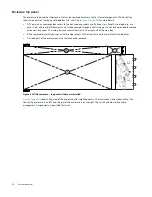
Overview of front panel LEDs
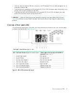
The enclosure front panel displays several LEDs. The front panel displays the functions shown in the illustration below
and listed in the table. See also
Figure 14 LEDs: 4U106 enclosure front panel
LED
Front panel functions
(lower left corner of panel)
LEDs as displayed in the output of the GEM CLI
command '
report_faults
'.
1
System Power (green)
Not reported
2
System ID (blue)
Unit Identifier LED
3
Host Connectivity (green)
Port Link Status Ops LED
4
Fault - Main Bay (amber)
Module Fault LED
5
Fault - Application (amber)
Logic Fault LED
6
Fault - Rear Module (amber)
Module Fault Rear LED
7
Fault - Auxiliary bay (amber)
Module Fault Side LED
1
3
5
7
2
4
6
Front panel – lower left corner
(partial view)

