34
System overview
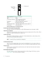
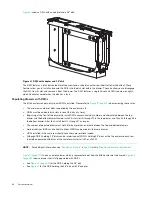
Figure 26 LEDs: Ops panel – 2U enclosure front panel
System Power On/Standby LED (green/amber)
LED displays amber when only standby power is available. LED displays green when system power is available.
Module Fault LED (amber)
LED illuminates when experiencing a system hardware fault. It may be associated with a Fault LED on a PCM or IOM that
helps the user to identify which component is causing the fault.
Location LED (blue)
When activated, the Identity LED blinks at a rate of 1s on, 1s off to easily locate the chassis within a data center. The
locate function may be enabled/disabled through SES.
NOTE:
The Location LED is not activated for this configuration.
Unit Identification Display
The UID is a dual seven-segment display that can be used to provide feedback to the user. Its primary function is to
display an enclosure unit identification number to assist users in setting and maintaining multiple enclosure systems.
Thermal sensor
The thermal sensor is located on the outside of the enclosure, and it sends input to the enclosure about its external
operating ambient temperature.
5U enclosure Ops panel
The front of the enclosure features an Operator’s panel located on the left ear flange of the 5U chassis as shown in
. The 5U Ops panel provides the following:
Ops panel functions
(see left ear on 2U front panel)
LED
Status
System Power On/Standby
Constant green: positive indication
Constant amber: fault present
Module Fault
Constant or blinking amber: fault present
Identity
Blue: power on (5s) test state
Unit Identification Display
Green (seven segment display: enclosure sequence)
Thermal sensor
Located behind panel
UID
Identity
Module Fault
System Power
Mute (not used)

